|
|
Post by glankford on Jul 30, 2012 19:28:54 GMT -5
Hello everybody, I'm 95% done restoring my re5, and I decided to re-do he ignition module with fresh electrolytic capacitors. Giving the box power resulted in a high pitched squealing. I guessed that sound wasn't normal. My ignition module isn't fully potted, only the caps. I was feeling ambitious and figured that it would be wise to replace them before trying to run, since it has been sitting for so long and electrolytics are known for drying out, especially when they've been sitting unpowered.
Long story short, I figured these caps would be labeled like every other capacitor I've seen. Well... not so much. After digging through the epoxy and mangling the caps, I found only one of them were marked (2.2uF @ 200V). The others were just blank aluminum cans.
Hmm.
If I can't figure it out, I'm going to do a little reverse-engineering of the circuit and try a few things. If that doesn't work, I'm in for the new full replacement module from Jess. Since I'm way over budget on this, I'm going to try the inexpensive route first.
Does anyone know the value of those caps?
Thanks,
Garrick
|
|
|
|
Post by bdalameda on Jul 30, 2012 20:34:50 GMT -5
High pitch sqealing is normal for the RE5 Ignition module. They all do it. Sorry but I do not know tha value of the caps. Others here probably do.
Dan
|
|
|
|
Post by goandy on Jul 30, 2012 22:50:18 GMT -5
Can't help you with the caps, but replace your diodes while you're at it. By the way, replacing the ignition with one like Jess's is a very good idea- well worth living on bread and butter for a few weeks to save up for it! Have you tested your unit to make sure it's working ok? There is a fairly simple circuit described in the service manual:  |
|
|
|
Post by goandy on Jul 31, 2012 22:08:38 GMT -5
I forgot to add- some multimeters can measure capacitance- if you can find one that can and the remaining unmarked caps aren't too mangled, you might be able to work it out...then post up for the rest of us...  |
|
|
|
Post by glankford on Aug 1, 2012 19:29:25 GMT -5
Hello andynogo, like an idiot I took a quick measurement and dismissed the readings as way too small to be correct. Because I was confident the values would be on the cans, I went ahead and dug in, destroying them. After learning that it was a high voltage circuit, I was kicking myself for tearing into it. The caps were physically large due to the high voltage rating.
Thanks,
Garrick
|
|
|
|
Post by goandy on Aug 1, 2012 22:40:23 GMT -5
Well then, post in Jess's thread below this as we speak.... ;-)
|
|
|
|
Post by glankford on Aug 20, 2012 18:24:56 GMT -5
andynogo, I couldn't find Jess's thread, but I do have an update.
So far, I have success! There were 3 caps buried in the epoxy. One is a mylar film 2.2uF @ 200V. That one is for the oscillator. There is a diode across it that is also buried in epoxy. The other two capacitors are for the discharge circuit. I did some digging around online and found typical CDI circuits. The most common one I found used a 1.0uF and 0.47uF. I hooked up a function generator to simulate the points opening and closing. That way I could run it through the RPM range and look for weird spots. I also hooked up the coil to a standard spark plug with the gap cranked way up. Upon power, I heard the happy singing and no smoke. So far so good. Running the function generator up and down there were no weird spots, so I'm calling it a tentative success. I'm doing throttle cable adjustment now, and I'm hoping to fire the bike up tonight.
[edit] i let it run with the function generator for about 15 minutes sparking away at a high speed. The capacitors didn't get hot and nothing let loose.
I replaced both electrolytic capacitors with mylar film capacitors, since capacitor technology has improved quite a bit, and the series resistance of electrolytics is pretty bad.
|
|
|
|
Post by goandy on Aug 20, 2012 19:37:15 GMT -5
Nice work! I was thinking of doing this to one of my CDI's- thanks for the values. Jess's thread (he is Rotary Recycle) is the one for the electronic igniton kit he sells- he needs ten people to make the run of plates for the points housing, I think he's got five or six people already. If you have a look in the for sale: cycles and parts section you'll find the "electronic ignition" thread. Not sure if you are aware but on the main page of the forum, if you click on the "new topics" on the list of options up there, it shows you the latest posts irrespective of where they are hidden in the forum! Excuse me if you already knew- it took me a while to clock that one... Oh, and by the way, re replacing caps, diodes etc, photos please or it didn't happen! ;D |
|
|
|
Post by wayne on Aug 20, 2012 23:02:42 GMT -5
Hi Andy, Unfortunately, that test circuit diagram is incorrect (Suzuki corrected it in a bulletin- finger trouble at the drawing board obviously). This is the corrected version: 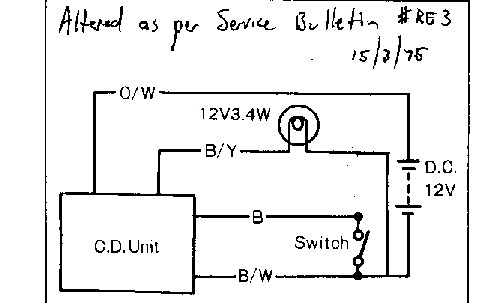 (We detail nerds have our place)  |
|
|
|
Post by goandy on Aug 21, 2012 0:54:10 GMT -5
Thanks Wayne! Took me a few looks to work out the change! I shall update the diagram in my book. Hope nobody blew up their CDI's using the wrong diagram.......  |
|
|
|
Post by glankford on Aug 22, 2012 15:56:44 GMT -5
Hello Andynogo, I would love some help figuring out how to post pictures. I just couldn't figure it out the one time I tried. I do have pictures of the disassembled module (for the purposes ot knowing what wires went where. I did not take pictures of the assembled part along the way, but I can mark up the pictures I had with the whole what-goes-where.
I did not know about the new threads thing. I'll try it out.
[edit] I wasn't able to run it through the entire RPM range as loaded on the engine, I just got it running 2 days ago. If I have any issues once I get it out on the road, I'll post.
Thanks,
Garrick
|
|
|
|
Post by goandy on Aug 22, 2012 18:53:20 GMT -5
Hey Garrick, Probbly the first thing is do you have an online library of pictures like on photobucket.com? The only way to post pictures on the forum (unless I'm wrong) i by inserting a web link:max-age=900 Server:Microsoft-WD There's a couple of ways to actually insert the photo- photobucket is quite handy as it pops up a little window when you hover your cursor over a photo and has various options. If you click on the information to the right of "IMG Code", your computer will copy the link, which looks like {IMG}http://i1899.photobucket..com/albums/z173/andynogo/273A7D60-DED1-4A39-89B5-6A87E1015DA7-17095-00002B913CF50256.jpg{/IMG} The important bit is the "{IMG}" and "{/IMG}" as this tells the forum to insert the photo at the web address inbetween them. You can then just ctrl+v paste this into your reply wherever you want the photo to go. Note that the img and /img should have square brackets either side of them, but I can't put them in as the forum then tries to interpret them as an image and they disappear! Clear as mud? The other way is to post a reply in the fully window (not the quick reply function), click in the "insert image" button above the text box and manually enter the web address where the photo is. Each photo needs its own "{IMG}" and "{/IMG}" (but with square brackets of course) and web address within them. Clear as mud? There are also other things to consider like making the images the right size for viewing on the web- that's something you can set when uploading to photobucket- it'll be one of the options in your settings and gives suggested settings to help you. This thread also describes how to attach a picture straight from your computer but I couldn't get my head around it on a quick scan. I never see an attachment option when I post so I just do it through photobucket.... re5rotary.proboards.com/index.cgi?board=info&action=display&thread=199 |
|
|
|
Post by glankford on Aug 24, 2012 18:27:59 GMT -5
|
|
|
|
Post by wayne on Aug 24, 2012 23:18:18 GMT -5
Thanks for the pics.
Geez, looking at that dining table, your wife must love you..........(pretty much the sort of thing that goes on at my place too).
|
|
|
|
Post by glankford on Oct 2, 2012 10:22:14 GMT -5
Just as a followup, I've been riding the bike for a few days (and winding it out a few times) and it seems to be all good! Thanks everyone for the advice! Now that I have the bike all put back together and all the striping on it, I'll have to post some pictures of the finished product.
|
|