
Post by wayne on Nov 27, 2022 19:17:10 GMT -5
Most of heard of the B point Speed Sensor in the M model Tacho. It's why you're B points won't work in an A model even if connected along with the speed relay under the tank.
You can thank member FRAMITRON for asking me to photograph the sensor while I had my instruments apart.
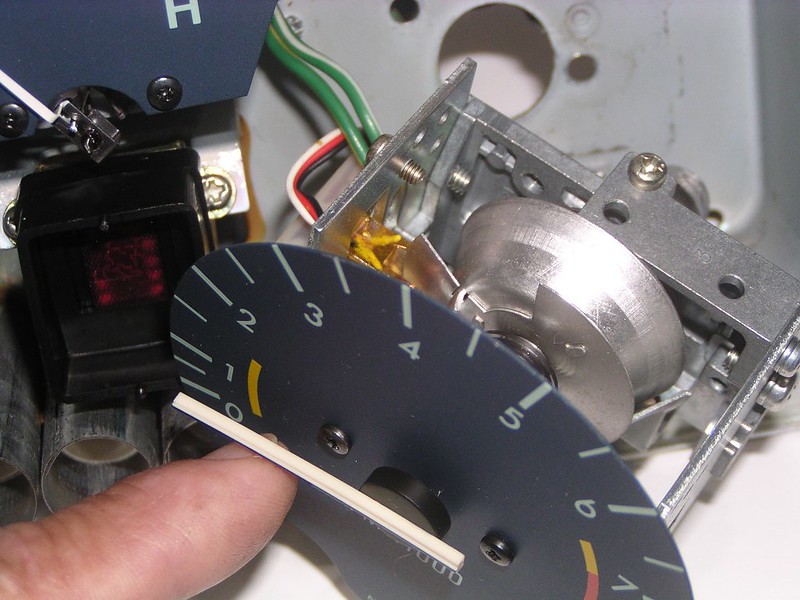
Simple mechanism. A metal disc of varying diameter rotates on the same shaft as the tach needle. It has a couple of "slices" taken out of it. At one point on its circumference where the radius is large, a disc segment passes through a U shaped device (some sort of Hall effect sensor). That goes into a tiny electronics box and wires out the back of the instrument tub.
When the disc segment is between the sensor, the circuit to the B points is open and they don't operate. As the RPM increases, the disc rotates with the needle until that segment clears the sensor, that part of the B point mechanism is now closed with the potential to make a circuit (remember it's also reliant on high vacuum so it alone won't activate the B points).
As the needle and disc rotate to higher rpm the radius of the disc near the sensor has reduced enough to clear the sensor completely (so the sensor sees nothing) leaving the B point circuit closed and ready.
The disc segment is cut so it's passing through the sensor from idle to 1700 rpm. Regardless of all other conditions, the B point circuit doesn't work in that band. Above 1700 rpm the segment clears the sensor and the B points are ready to work when the vacuum sensor behind the radiator senses an overrun condition (high vacuum). As the rpm reduces on overrun, the B points continue to work until, at 1700 rpm, the segment enters the sensor and cuts out the circuit returning the engine to firing on every face on overrun.
Looking from above the "U" block sensor is clear to see. You're looking at the thin metal disc edge on:

Note the rpm needle at idle. Behind the "4" on the tacho face you can see there's a segment of the disc in the gold/brown sensor:

Due to parallex, the tach needle doesn't look it but it's at 1200 rpm, book idle. The disc segment is still in the sensor:
Once again parallex but that's 1700 rpm. You can see the edge of the segment leaving the sensor:

Now it's well clear at higher rpm:

Well into the rev range you can now see the remainder of the disc is smaller in radius and continues to clear the sensor leaving the points potentially active:

The magic box:

You can thank member FRAMITRON for asking me to photograph the sensor while I had my instruments apart.
Simple mechanism. A metal disc of varying diameter rotates on the same shaft as the tach needle. It has a couple of "slices" taken out of it. At one point on its circumference where the radius is large, a disc segment passes through a U shaped device (some sort of Hall effect sensor). That goes into a tiny electronics box and wires out the back of the instrument tub.
When the disc segment is between the sensor, the circuit to the B points is open and they don't operate. As the RPM increases, the disc rotates with the needle until that segment clears the sensor, that part of the B point mechanism is now closed with the potential to make a circuit (remember it's also reliant on high vacuum so it alone won't activate the B points).
As the needle and disc rotate to higher rpm the radius of the disc near the sensor has reduced enough to clear the sensor completely (so the sensor sees nothing) leaving the B point circuit closed and ready.
The disc segment is cut so it's passing through the sensor from idle to 1700 rpm. Regardless of all other conditions, the B point circuit doesn't work in that band. Above 1700 rpm the segment clears the sensor and the B points are ready to work when the vacuum sensor behind the radiator senses an overrun condition (high vacuum). As the rpm reduces on overrun, the B points continue to work until, at 1700 rpm, the segment enters the sensor and cuts out the circuit returning the engine to firing on every face on overrun.
Looking from above the "U" block sensor is clear to see. You're looking at the thin metal disc edge on:
Note the rpm needle at idle. Behind the "4" on the tacho face you can see there's a segment of the disc in the gold/brown sensor:
Due to parallex, the tach needle doesn't look it but it's at 1200 rpm, book idle. The disc segment is still in the sensor:
Once again parallex but that's 1700 rpm. You can see the edge of the segment leaving the sensor:
Now it's well clear at higher rpm:
Well into the rev range you can now see the remainder of the disc is smaller in radius and continues to clear the sensor leaving the points potentially active:
The magic box:


 ]
]