rebm
1st Gear

Posts: 21
|
Post by rebm on Dec 27, 2023 16:55:08 GMT -5
Time for an update. After reading all carb info from this board and from the Suzuki documentation, next job was overhauling the fuel system Fuel level sensor has all the common issues, it isn't functioning and is leaking Disassembled sensor with the NTC thermistor
The only 1K NTC I could find with axial connecting pins was with glass insulation. I first tried this but this wasn't functioning a supposed with the small 3.4W light bulb, with a stronger light it worked ok. In the end I used a 1K NTC with polyester insulation and parallel pins. With small round nose pliers I bend the pins in the axial direction. Almost finished sensor with new cable sleeve, wires & connector. I used JB-weld to seal around red plastic insulator Fuel tap before cleaning Cleaned fuel tap ready for assembly Carb before overhaul Disassembly of choke lever and cover Disassembly of carb Cleaned choke cover Carb body is also cleaned and ready for assembly after parts arrive back from the zinc plating shop
|
|
rebm
1st Gear
Posts: 21
|
Post by rebm on Jan 2, 2024 15:53:05 GMT -5
In the meantime I could further strip down the engine. Below are some pictures of this Rotor housing removed from frame and main case Starter motor removed and disassembled Oil regulator removed Cleaned and zinc plated oil pressure switch Cleaned gearbox brackets
Gearbox and main case removed from the frame Inside of the gearbox looks alright After this I bead blasted some engine parts Next job is disassembly of the rotor. With a steering wheel puller combined with an impact puller and some heat I could remove the counter weight on the right side. The counter weight is (nodular) cast iron, it has some strength and impact resistance but you have to be careful
Left counter weight removed Pulling off the left side housing First look on the inside. At one rotor tip the left and right side seal are stuck due to some carbon build up
I used a Suzuki front axle with an impact puller to remove the long dowel pins. One was very tight. The front axle has M12x1.5 screw thread and didn't fit very well into the dowel pin, I think the dowel pin has 1/2" UNF inner thread
On the side of the combustion area the O-ring starts to fail, the O-ring was brittle and some oxidation is visible on the aluminium housing on the coolant side
Optical the coating on the housing and side housings looks to be in good shape There is only some corrosion damage in the coolant channel of the right side housing. I quickly bead blasted this spot before it will be welded and machined Last job was removal of the shaft from the rotor and removing the oil seals on the side |
|
rebm
1st Gear
Posts: 21
|
Post by rebm on Jan 7, 2024 15:31:59 GMT -5
Next job before reassembly of the engine will be measuring of all engine parts and check this with the wear limit in the service manual. I also was wondering how others have re-tighten the nut of the left counter weight. Just tighten it with an impact wrench, or use a torque wrench and tighten it with 400Nm and hold it with a counter weight restrainer as mentioned is the rotary engine service manual? Besides this, I'm also looking for the drawings of the seal ring compressor tools, can anyone help me with this?
|
|
|
|
Post by wayne on Jan 7, 2024 17:18:08 GMT -5
Thank you for your continuing and excellent posts. There are several members who may be able to help with your questions but who aren't very active on the Board. I'll contact them and see if they can help answer those questions and/or provide the diagrams.
|
|
|
|
Post by wayne on Jan 7, 2024 17:34:20 GMT -5
|
|
|
|
Post by wayne on Jan 8, 2024 21:05:59 GMT -5
REBM here are some answers from FB re your flywheel question. There are people who have used just a rattle gun but I think the best answers are below. Pay particular attention to Peter Paul, he's on this Board and is very experienced with RE5 engine work. Andy is also on the Board but he's an Aussie so "F.T." translates as "very tight" and I'm being very polite!: 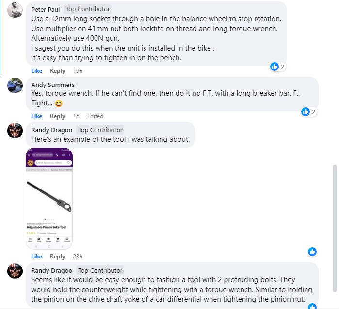  |
|
rebm
1st Gear
Posts: 21
|
Post by rebm on Jan 9, 2024 15:43:23 GMT -5
Wayne, thank you for your help. With the pictures of the seal ring compressor tools I can make the laser cutting drawings. At the same time I also can make a tool to hold the counter weight. I think I'm gonna use a torque wrench without a torque multiplier
|
|
|
|
Post by janski on Jan 22, 2024 13:47:10 GMT -5
Just an observation about the early side plates displayed, are these as durable as the spirograph variety?
|
|
rebm
1st Gear
Posts: 21
|
Post by rebm on Jan 28, 2024 8:17:41 GMT -5
Just an observation about the early side plates displayed, are these as durable as the spirograph variety? I think they are just as durable or maybe even better. I guess the pattern was just to save production time and cost. The early ones are fully coated which means more contact surface and also less edges where the coating can start to fail |
|
|
|
Post by janski on Jan 28, 2024 11:36:48 GMT -5
I can believe your guesstimate, and all the very best with your restoration.
|
|
|
|
Post by hudson on Jan 28, 2024 16:57:11 GMT -5
My understanding of the two different side plate coating designs ( Which I think came from this site ) is that the fully coated plates were not transferring heat from the rotor as well as the engineers would have hoped, so the spiral pattern was to increase heat transfer by exposing aluminum but still protect from wear with the ( moly I think ) inlay.
Brian
I accidentally like my own post when I was editing 
|
|
|
|
Post by janski on Feb 18, 2024 6:14:22 GMT -5
A very clever design, has anyone observed this in other rotary engines?
Great work at saving another REBM.
|
|