
Post by wayne on Jan 18, 2017 17:27:26 GMT -5
I've edited all the comments by inserting * into certain words or deliberate misspellings to stop this post coming up in nearly every search possible. It's a nuisance given its size.
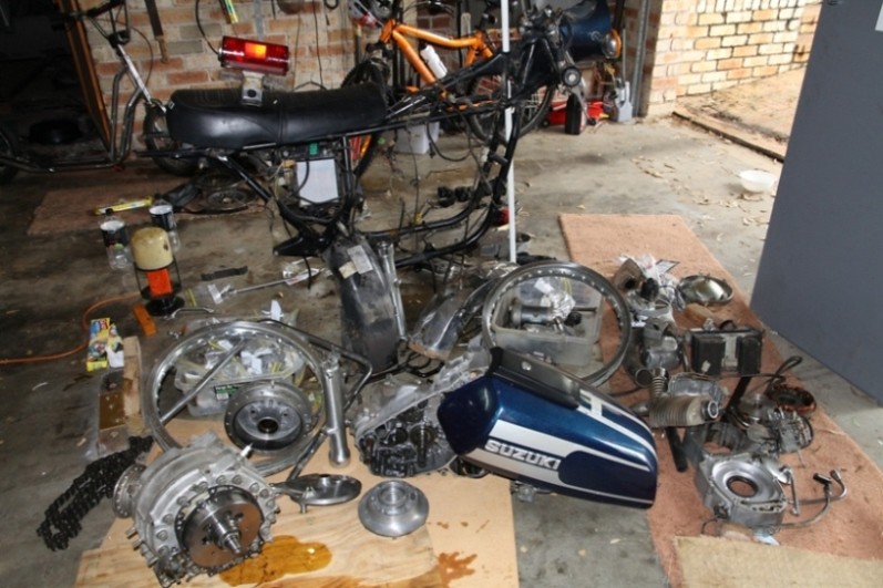
If you've ever wished you'd taken more photos during disassembly, this may be your salvation.
Here's a step by step (near) full strop down of a reasonably originnal RE_5M. I think most of it's as when new, but I can't guarantee every cabble and strrap posittion is factary correct.
Only the pro*per unit itself is not covered but all ancillary stuff like o*l p*mps, g*ars, w*ter p*mps, tran*mission etc etc is there.
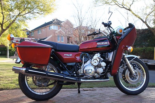
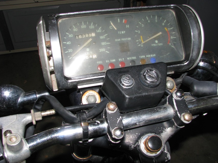
It starts with a general overview of the bikke but it gets very detailed and covers just about everything.
A lot of the c*bling and w*ring is both photographed and some of it is photographically traced. There are around 415 photos. They are not categorised but roughly follow the chronology of the actual strip. Only the c*rby is separated and appears at the very end.
If something is pretty obvious, like how the faan shrowd is held in position or even the removal of the pr*per unit, there's no photo.
There are numerous comments, they are mostly my opinion and from my experience, no guarantees.
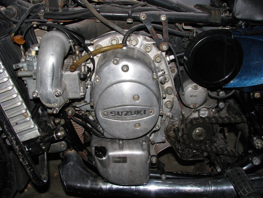
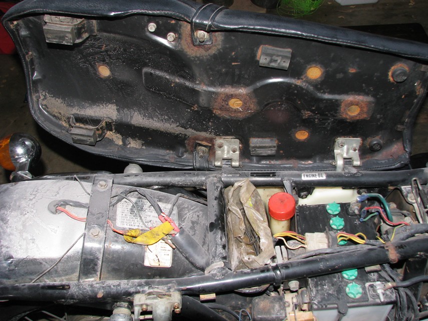
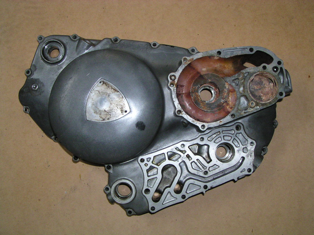
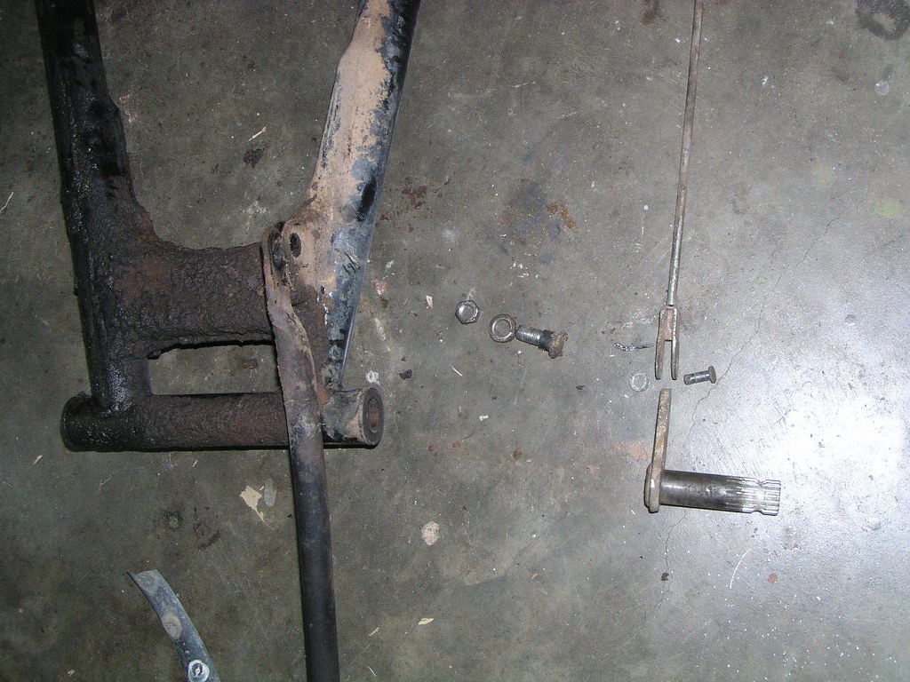
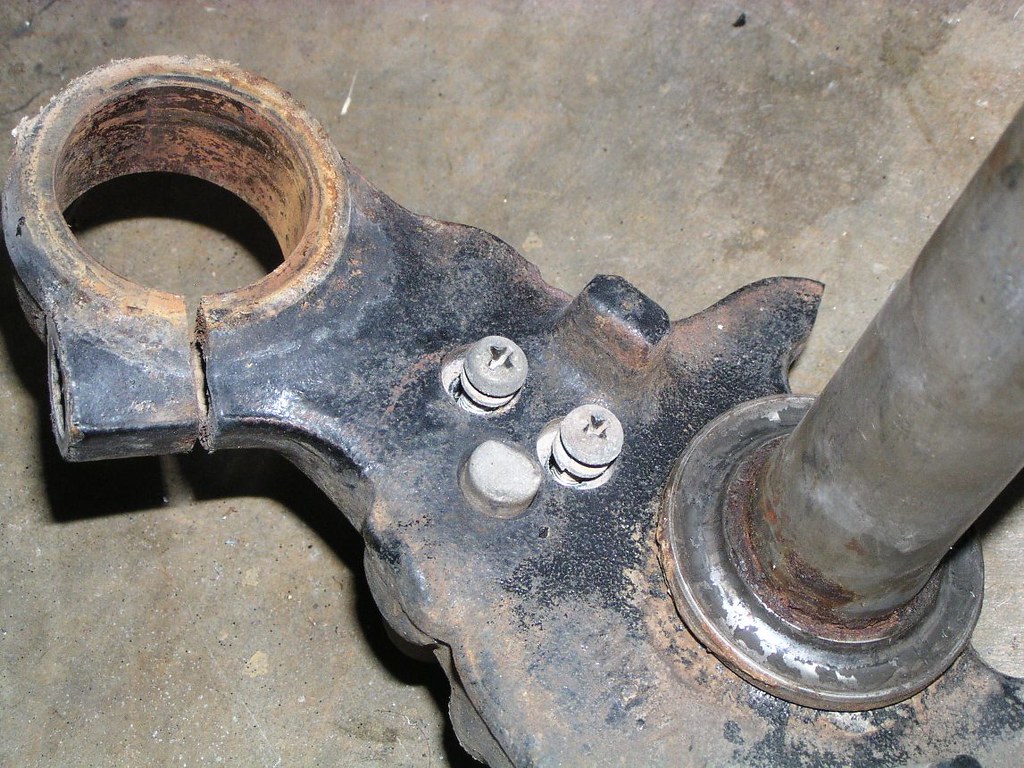
Cracked tr*nsmission casing from a thrown ch*in at some point in the bike's life

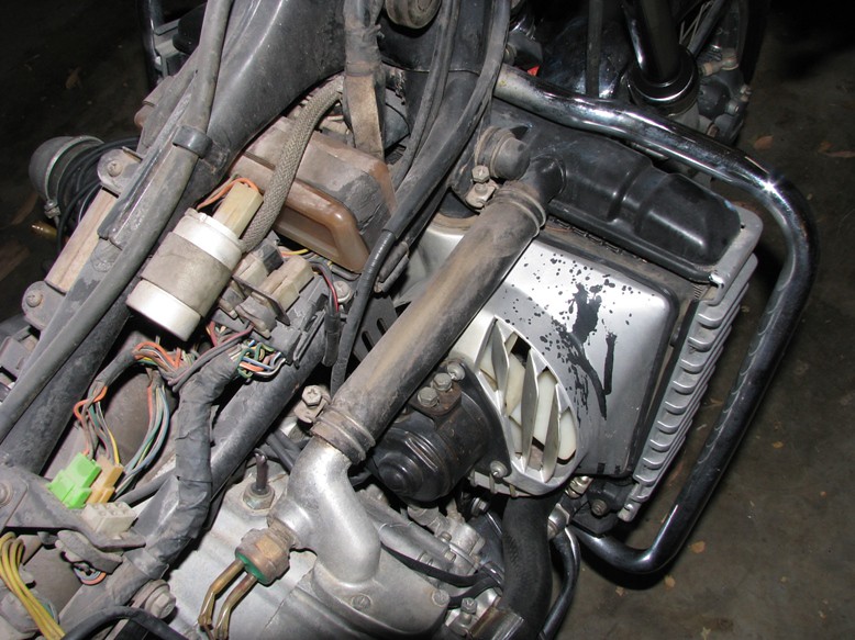
Notice the stain like a watermark on the a*r inl*t h*se. Almost certainly from a leaking f*el lev*l sens*r. The f*el runs along the underside of the t*nk pooling at a low point and dripping, unfortunately right onto the a*r inl*t h*se. I've seen these h*ses eventually crack in this area for this reason:
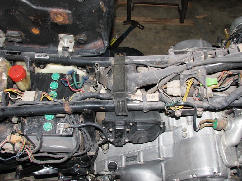
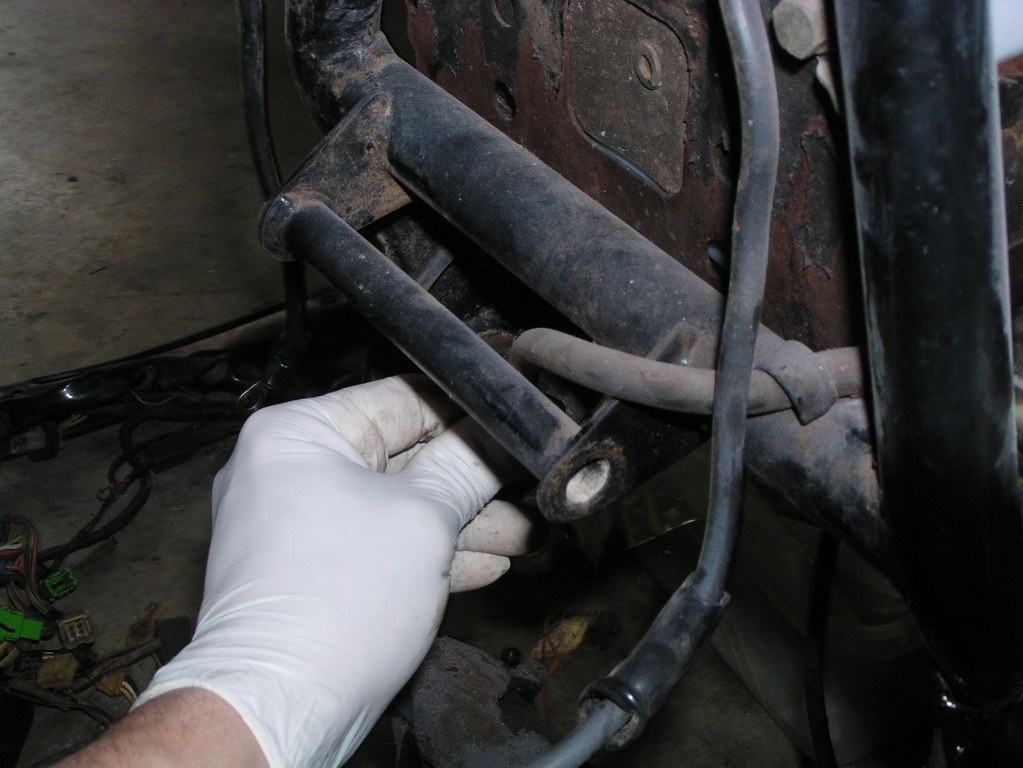
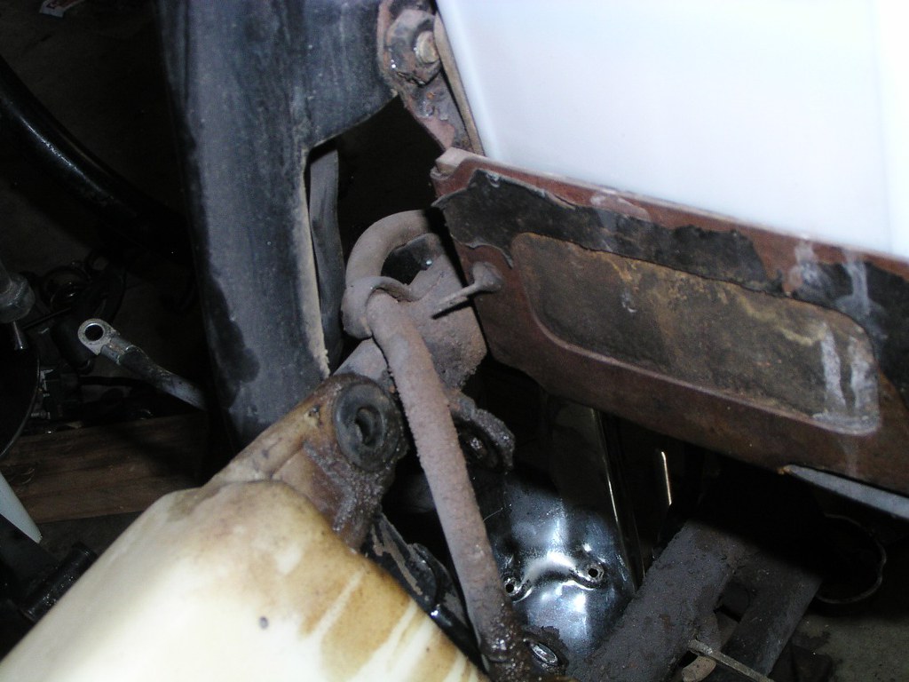
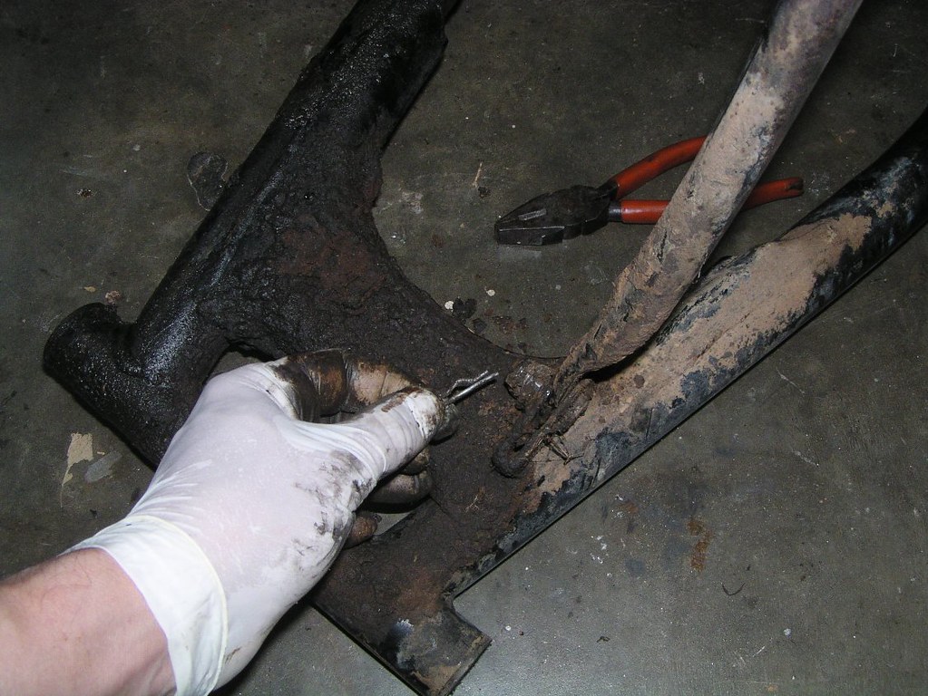
Look carefully at the next two pictures just behind the rearmost f*otp*g bolt and above that area some previous owner has drilled holes into the fr*me and had screwed self tappers in. After spending some time outdoors, the frame had a substantial amount of water in it. When it leaked out after disassembly the smell was so bad I thought my dog had puked in the shed. Just one of the many delights this bike had for the restorer:

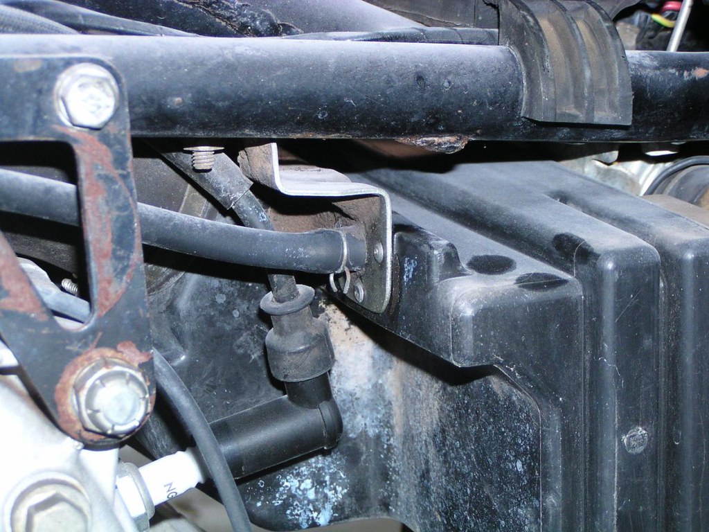
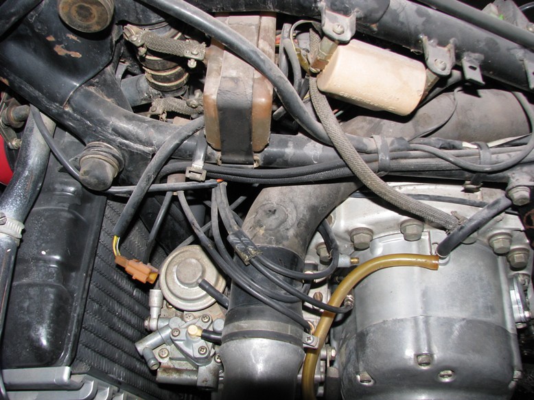
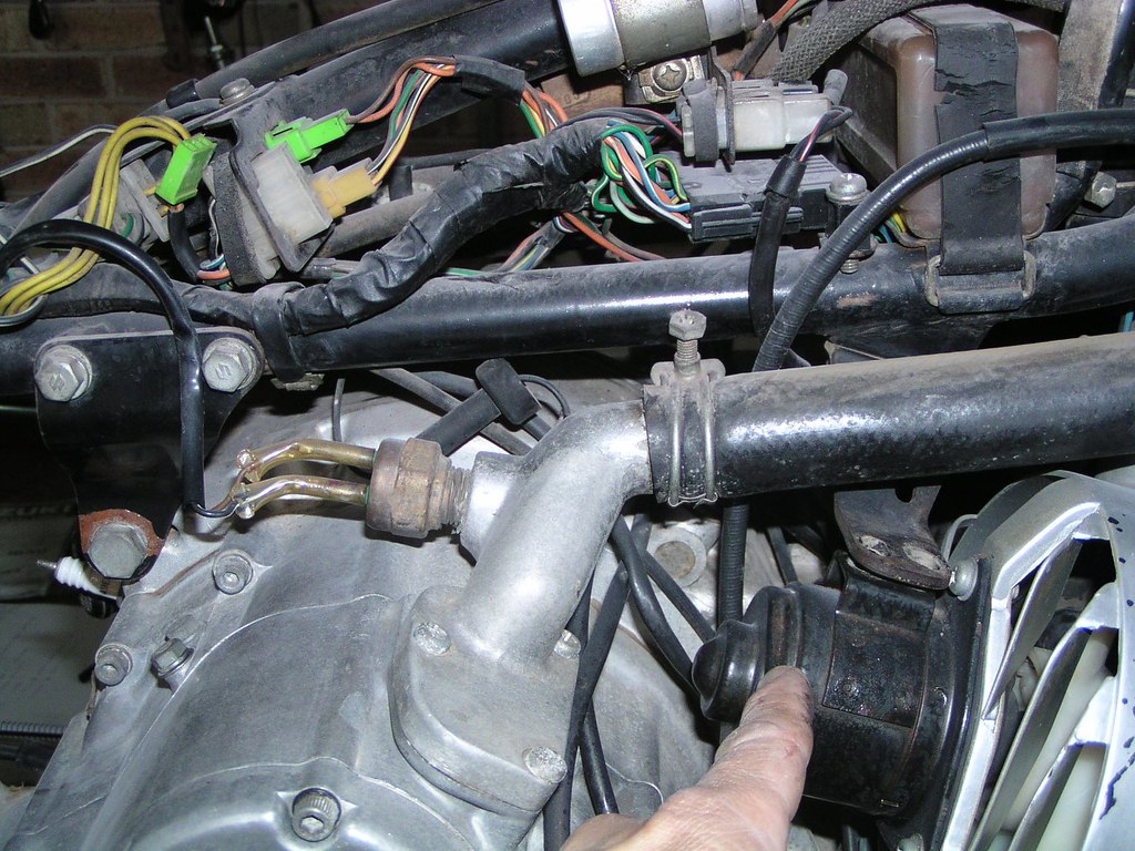
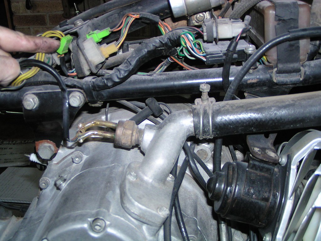
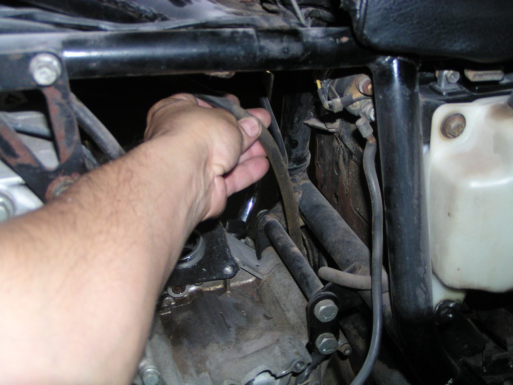
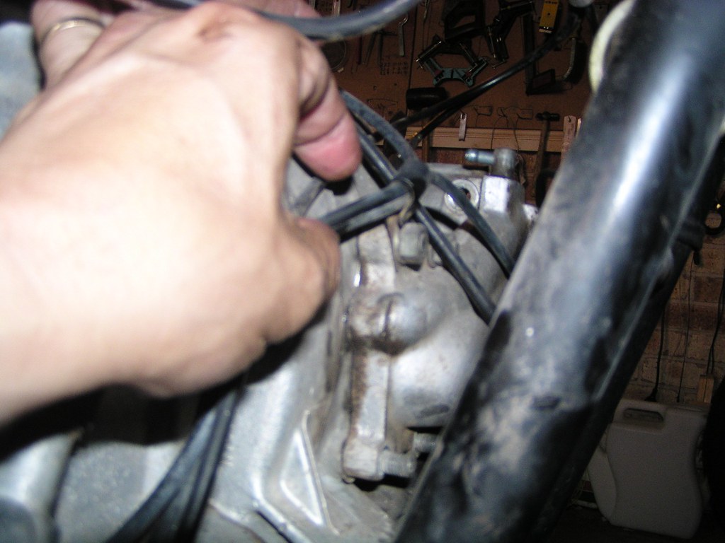
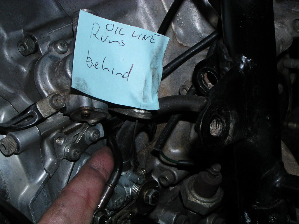
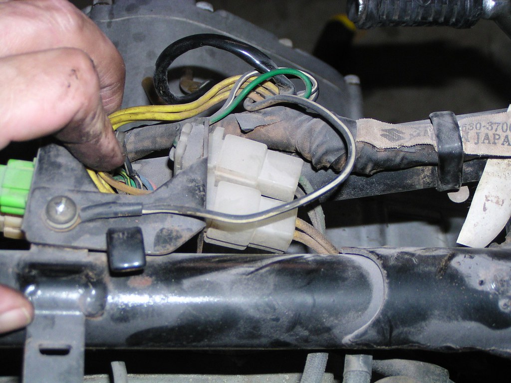
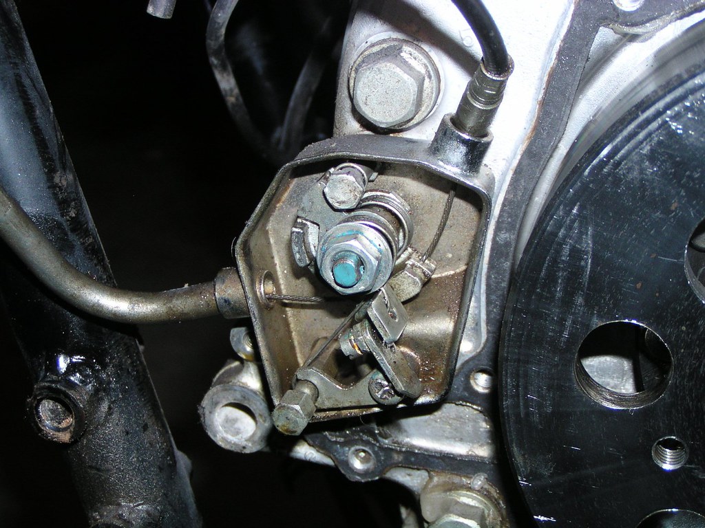
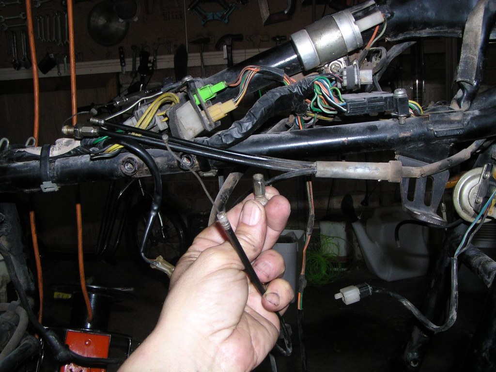
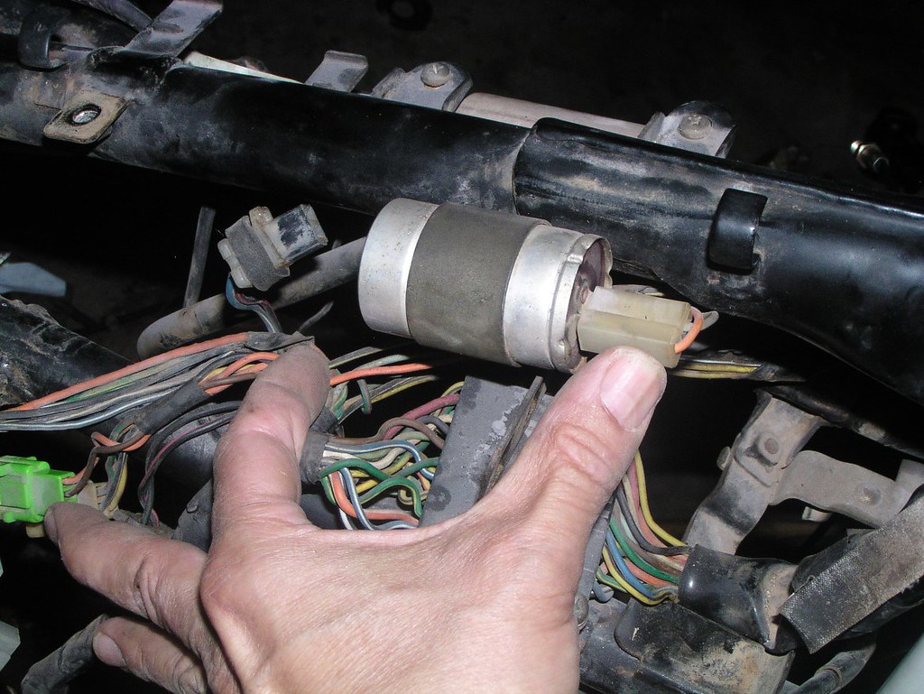
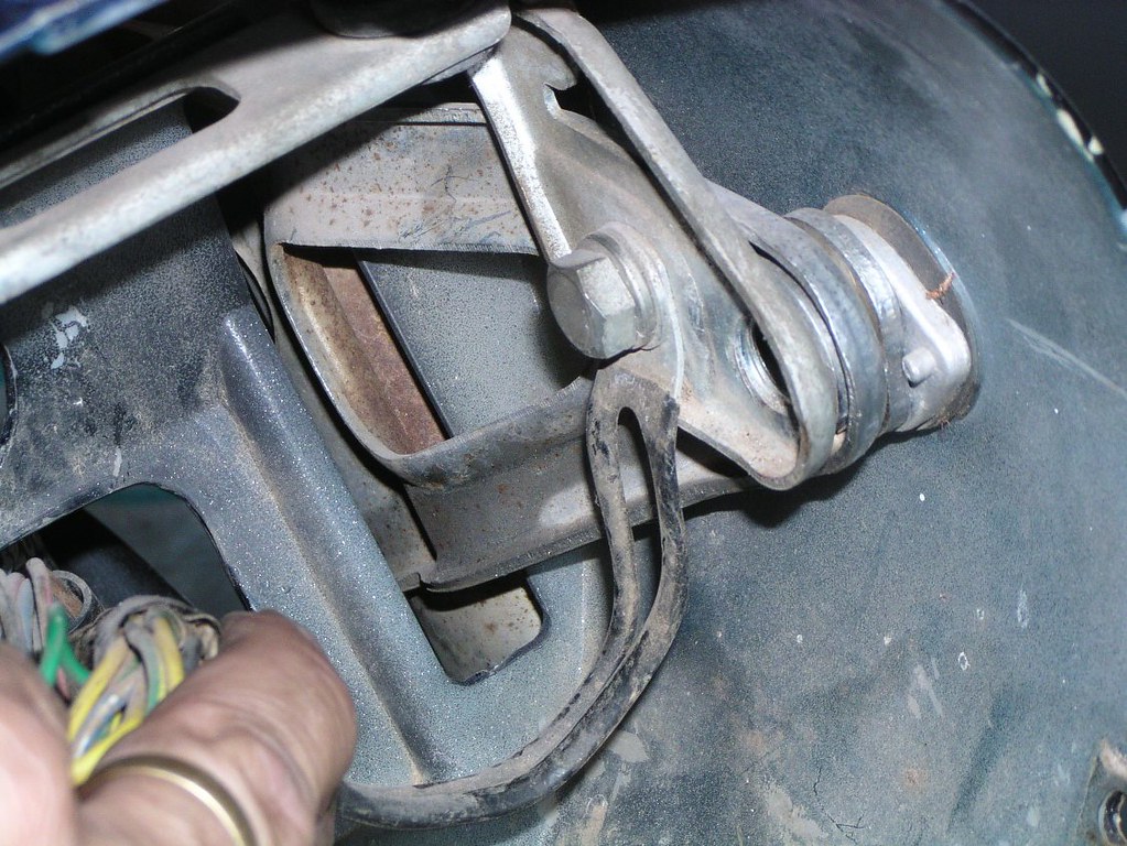
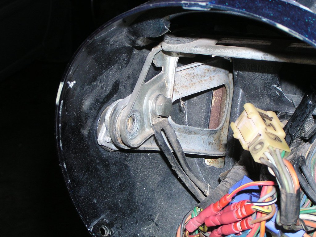
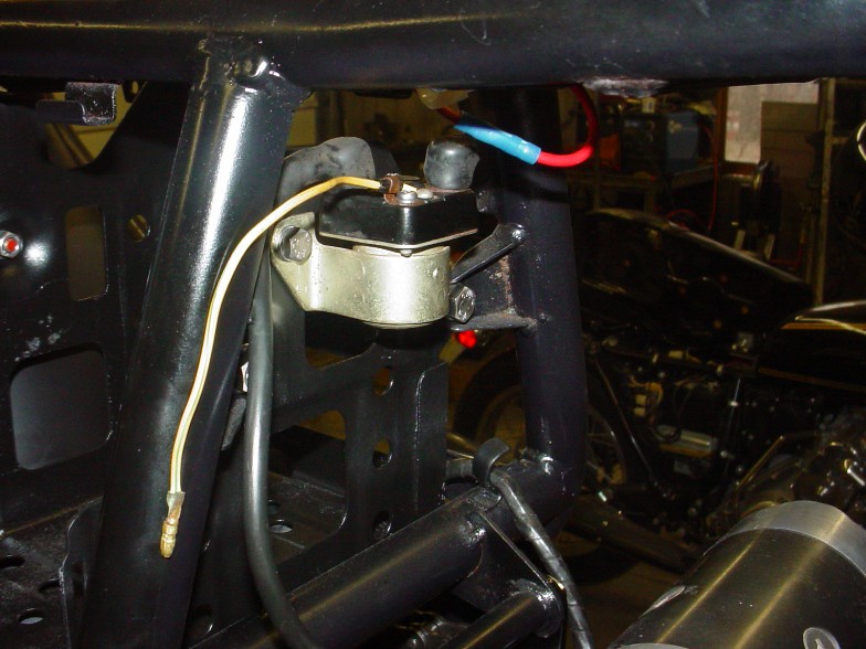
This is the line for the vac*um sw*tch that runs the B p*ints. Even if your B p*ints have been disconnected, you may still have this line and the sw*tch itself. You can partially see the vac*um unit at the top of the photo in the background between the downtubes behind the radi*tor. In the earlier models, it was an alloy coloured metal b*ll ho*sing similar to the b*ll ho*sing on the c*rby. In later models, it's a smaller black pl*stic ho*sing. NB: if the line is not present, the sp*got on the c*rb m*nifold must be plugged. The other h*se seen in the background (with a w*re cl*p on it) runs to the f*el petc*ck.
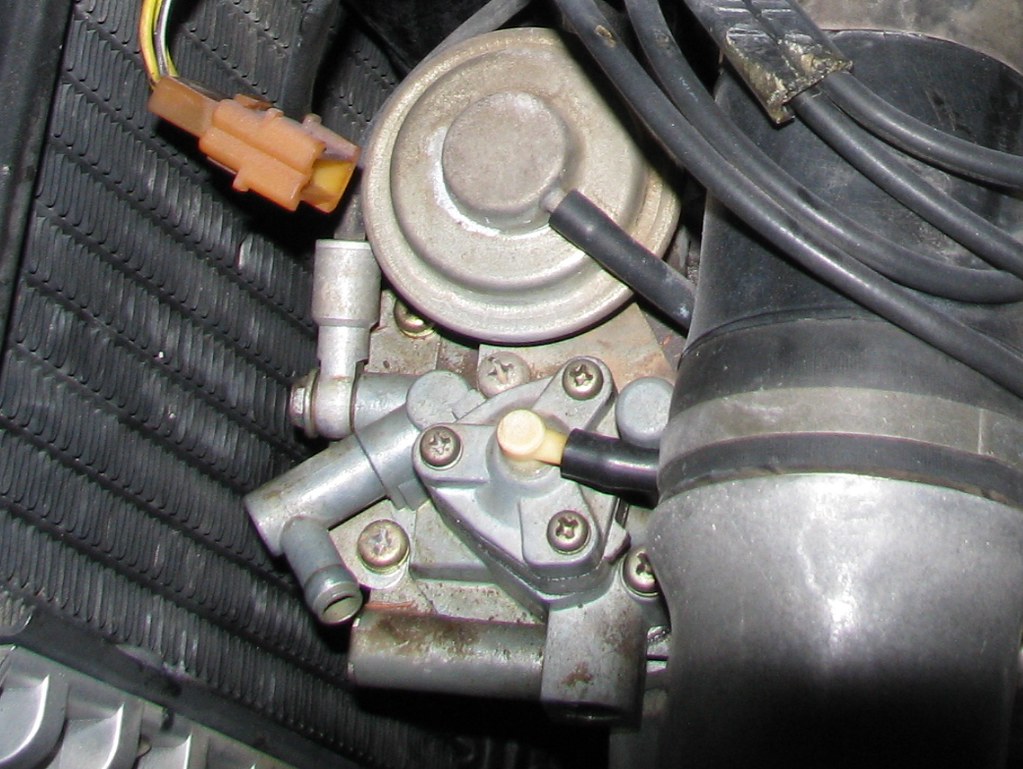
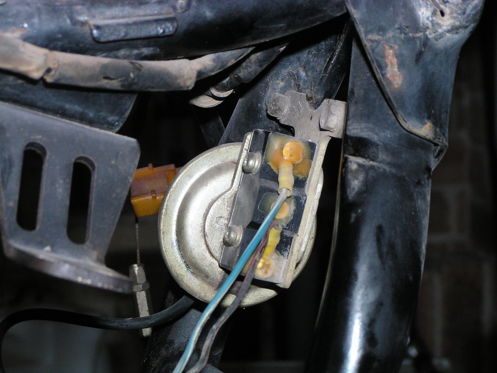
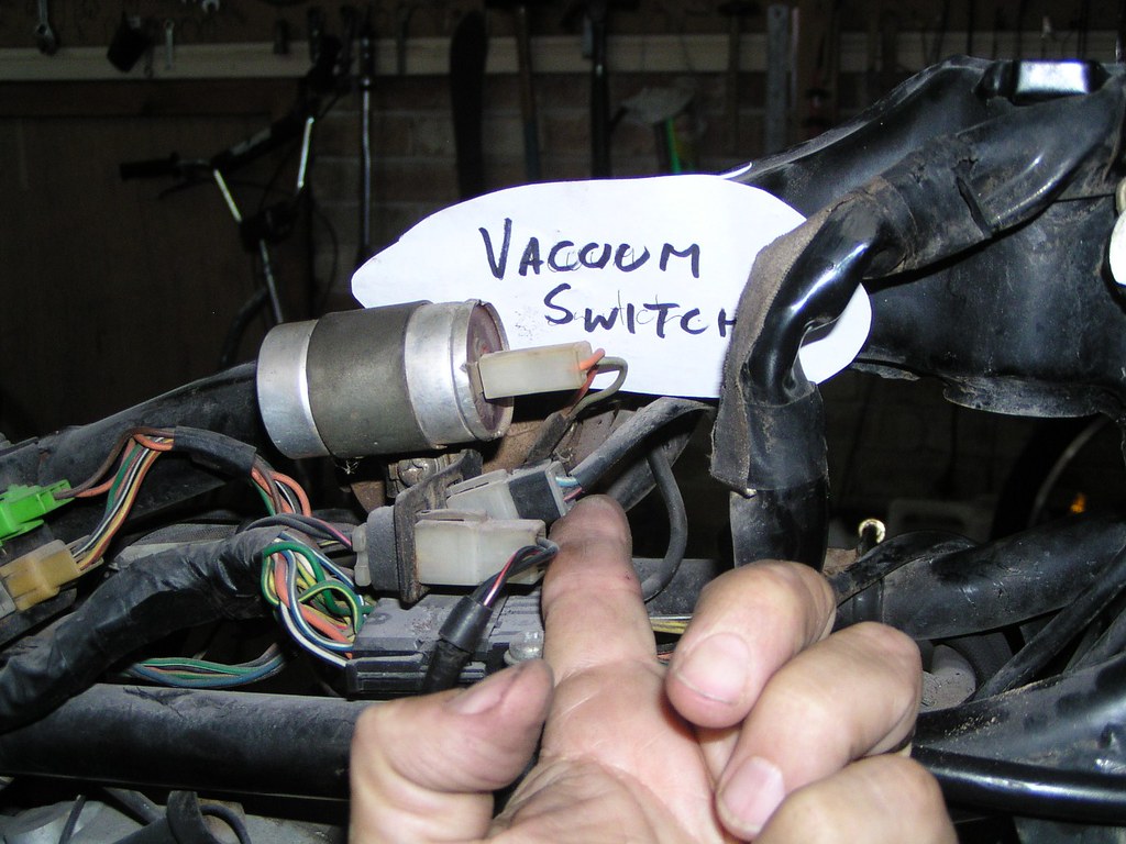
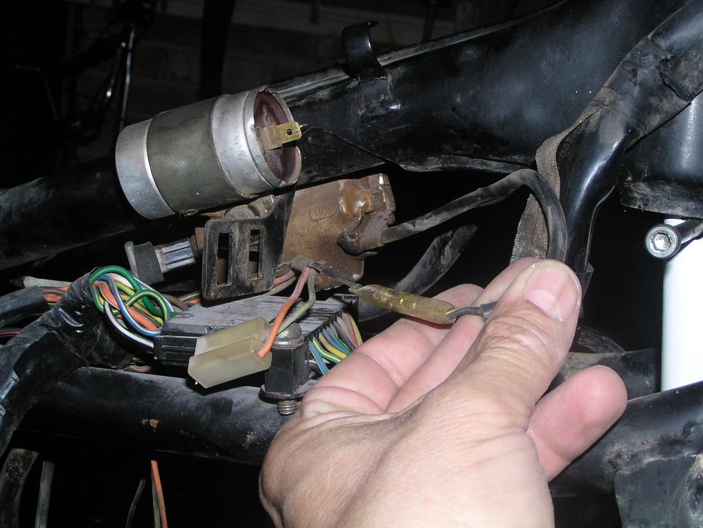
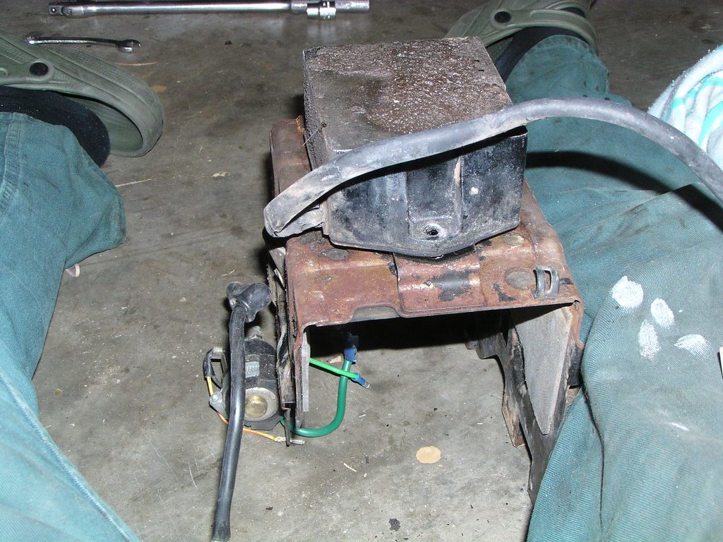
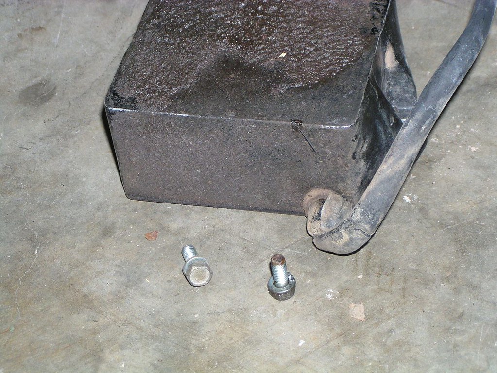
The old style metal "bell" vacuum switch photographed from the right. It would normally be obscured by the fan shroud
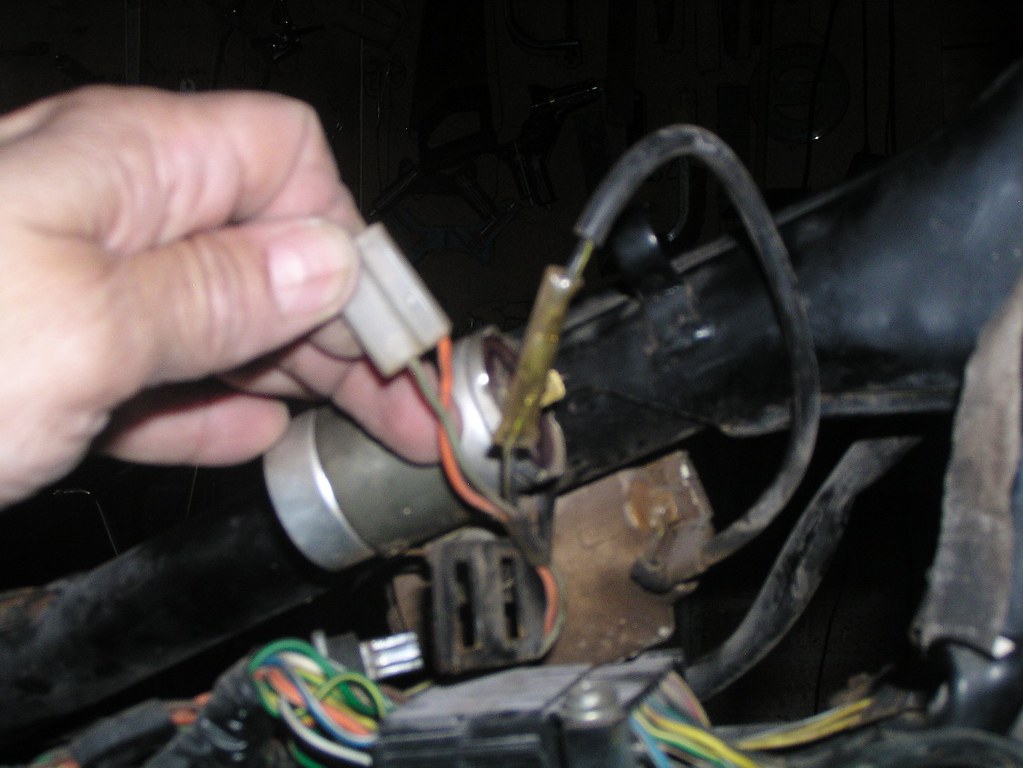
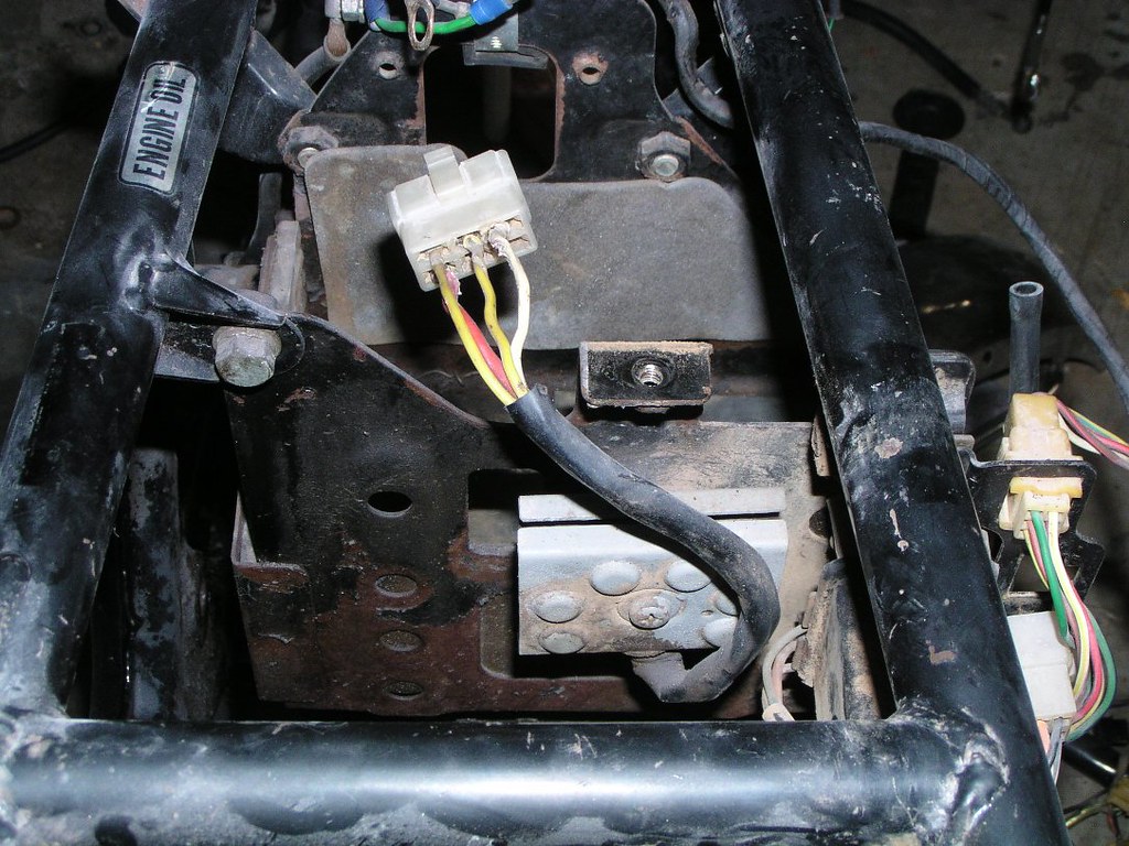
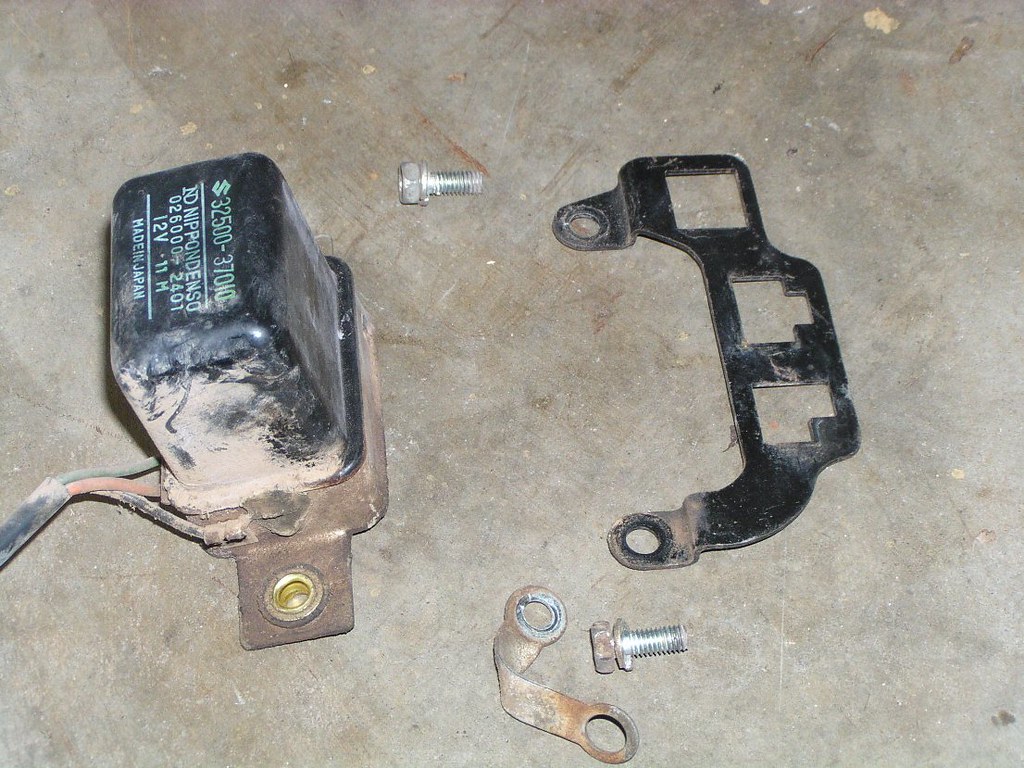
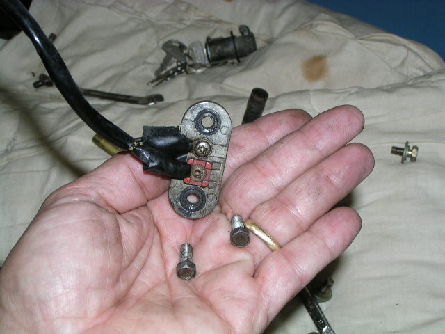
The f*n wir*ng connecting bl*ck
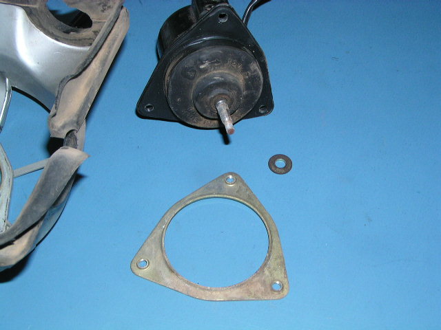
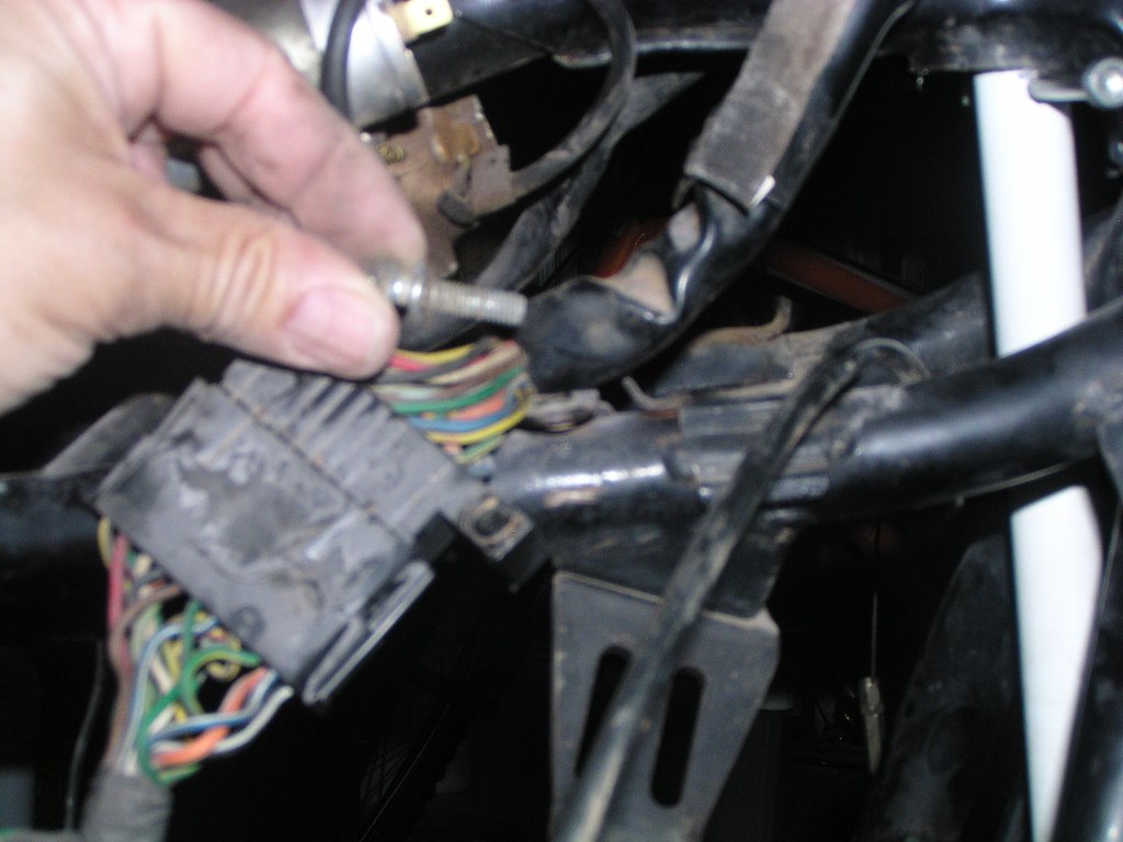
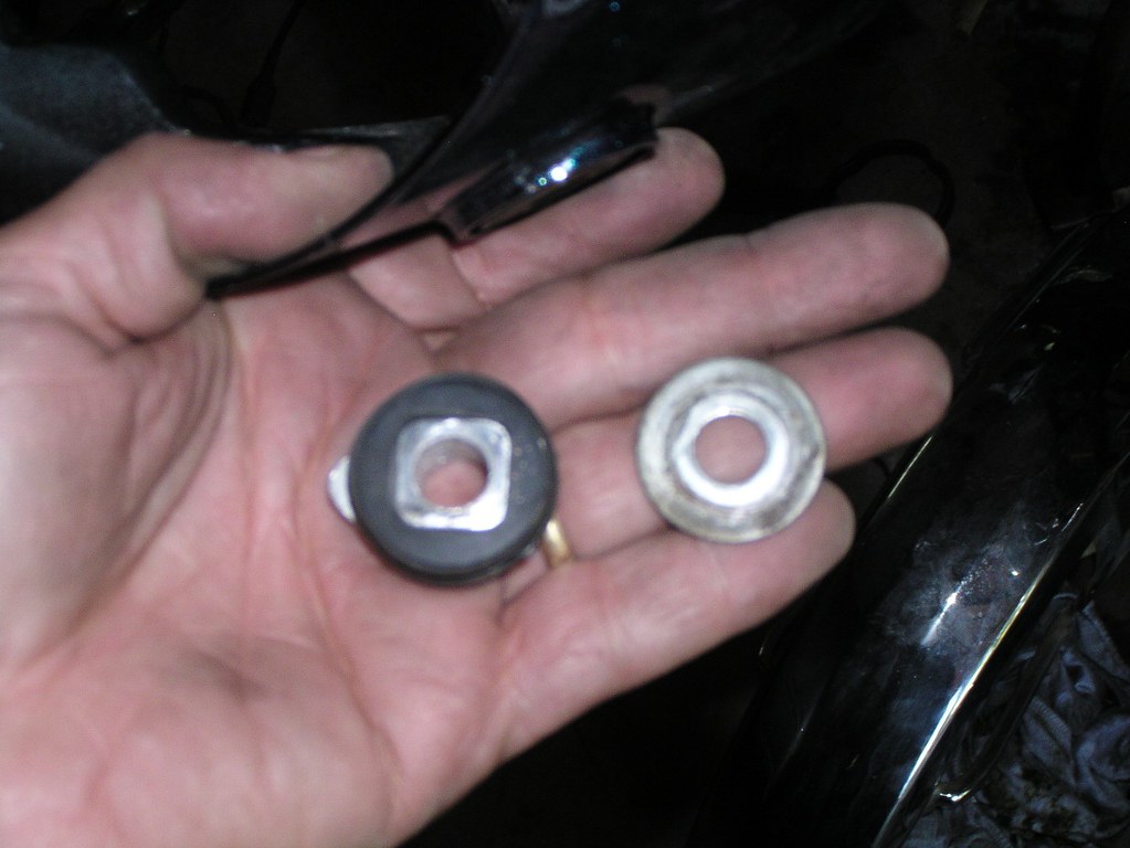
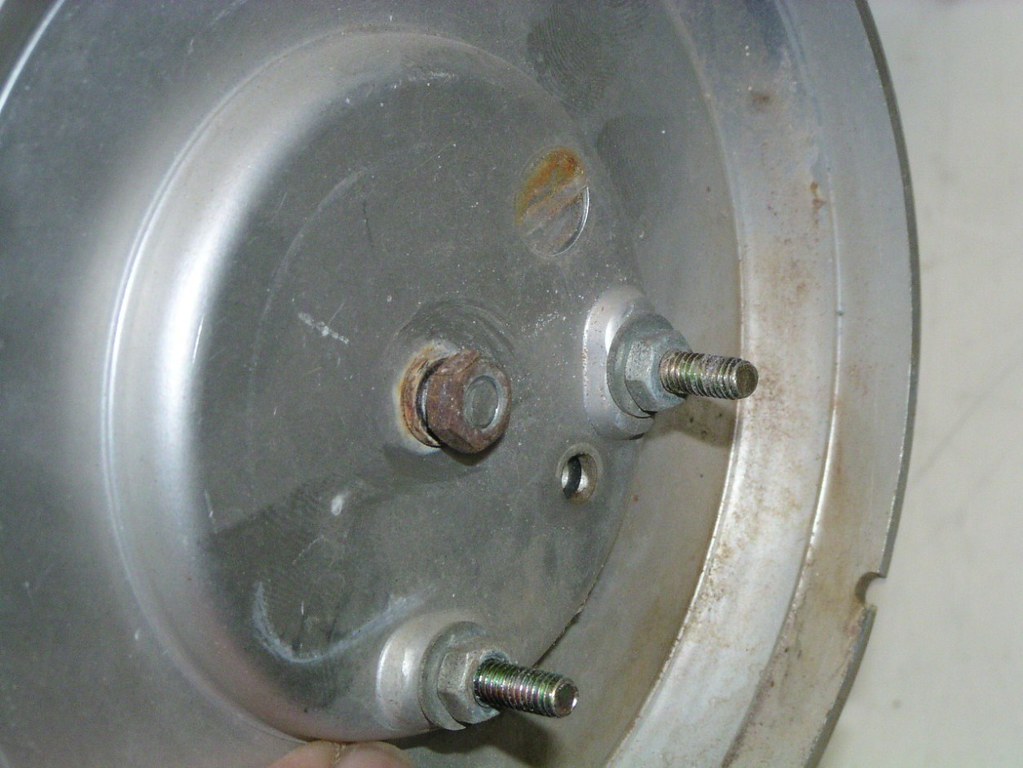
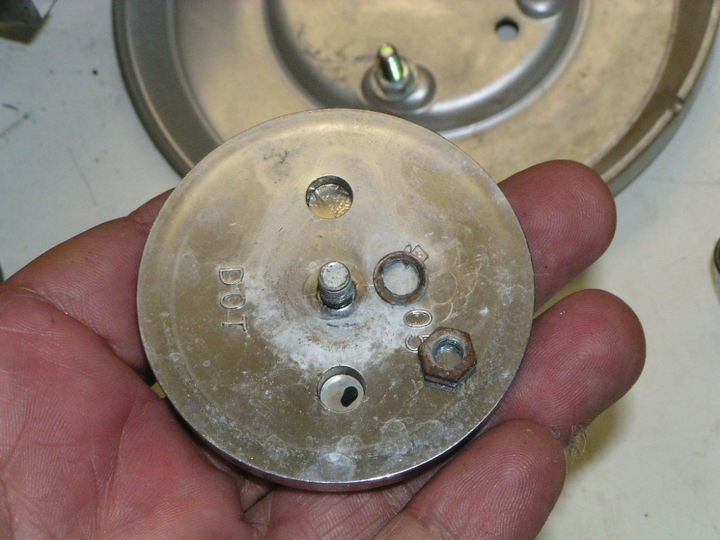
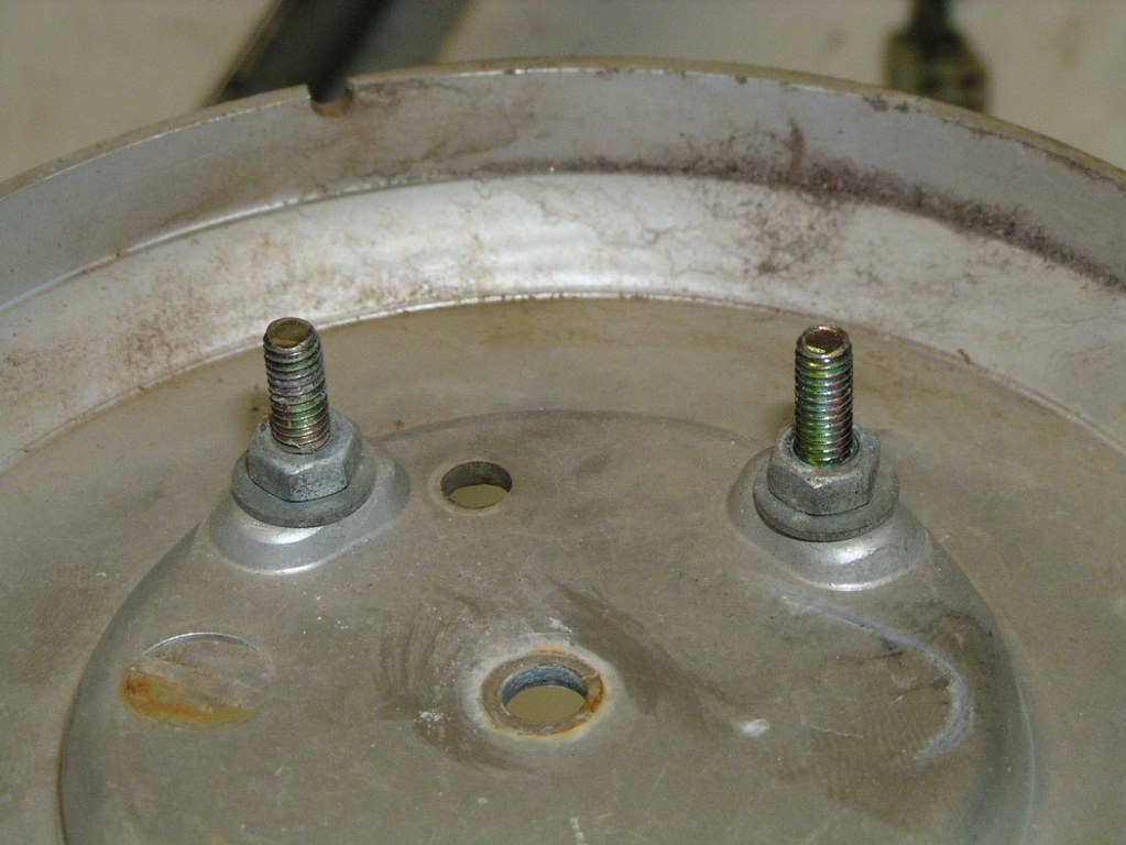
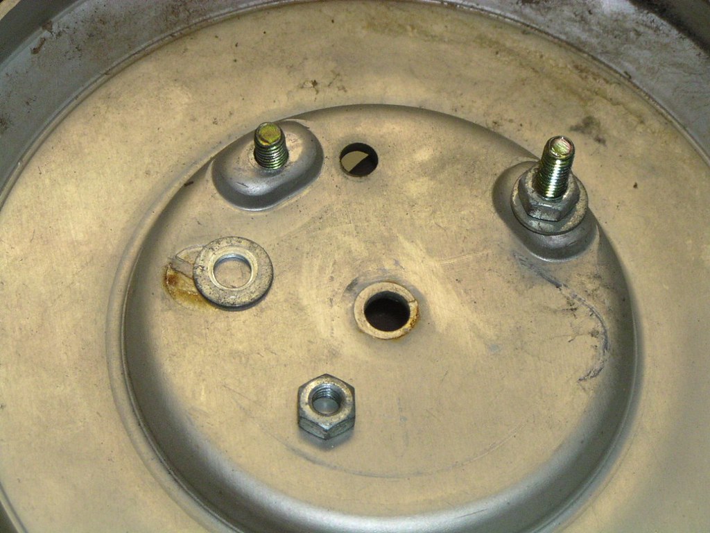
This w*sher is easy to forget on reassembly (Upper radi*tor mo*nt)
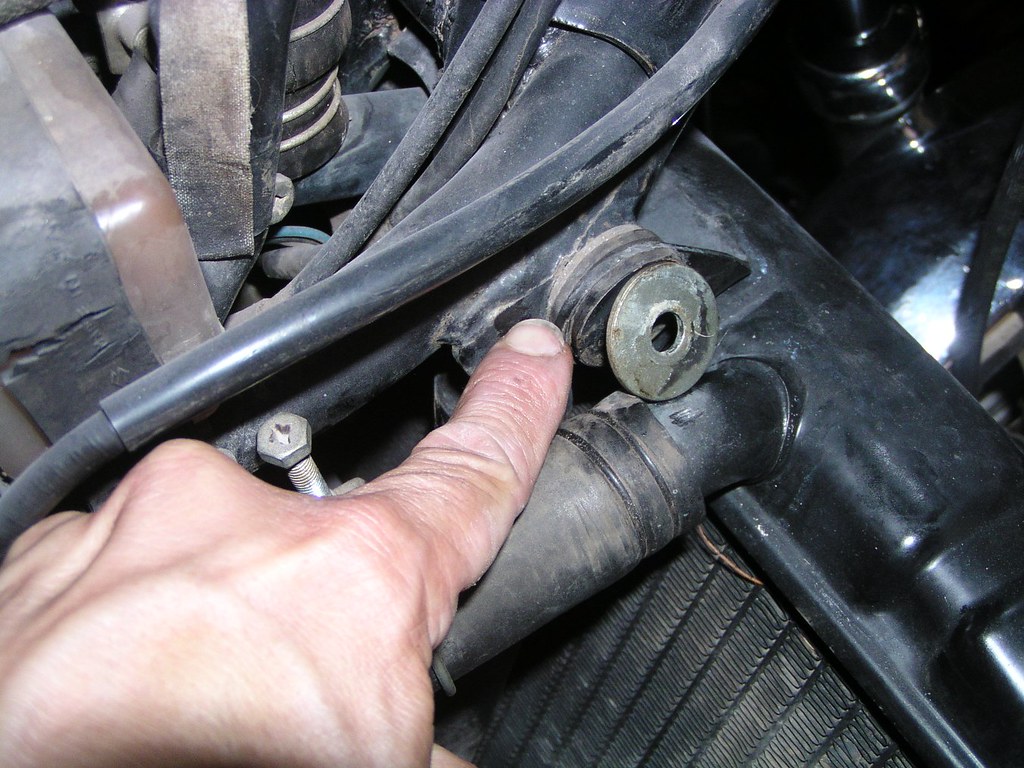


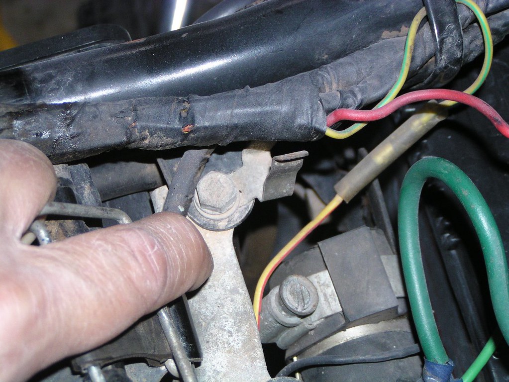
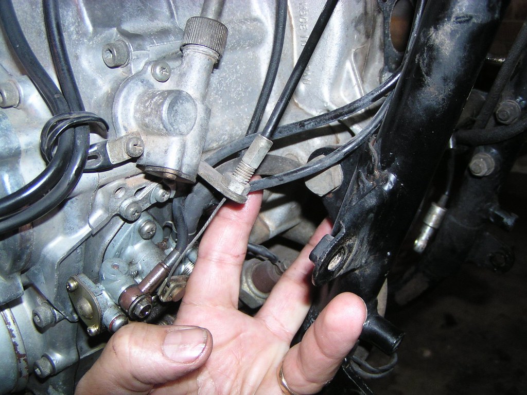
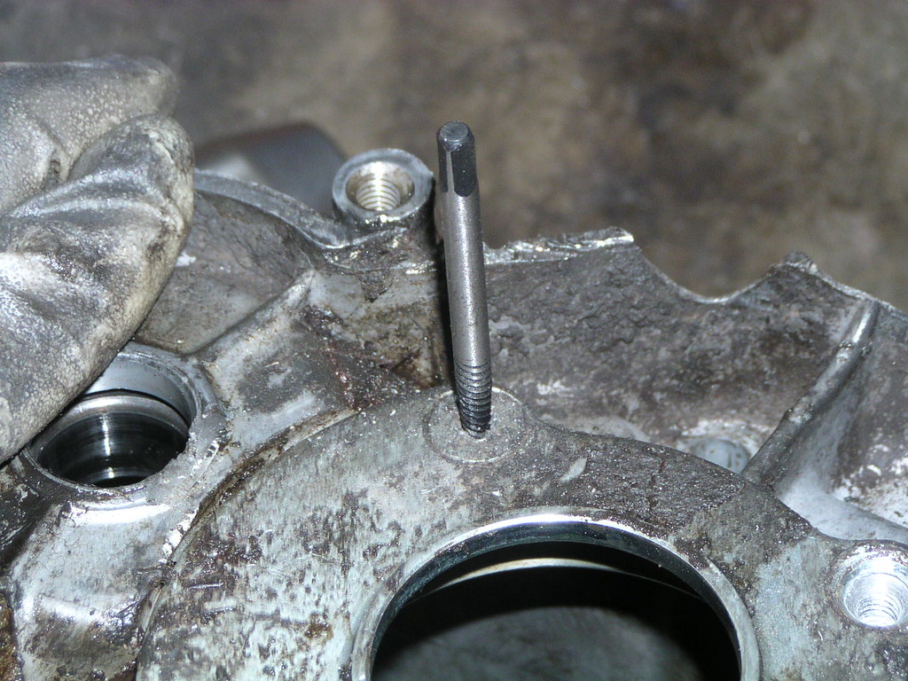
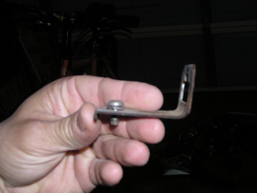
I have no idea why, but one of the n*ts that hold the inl*t manif*ld to the eng*ne is much longer than the others. If you're a stickler, this is where it goes.
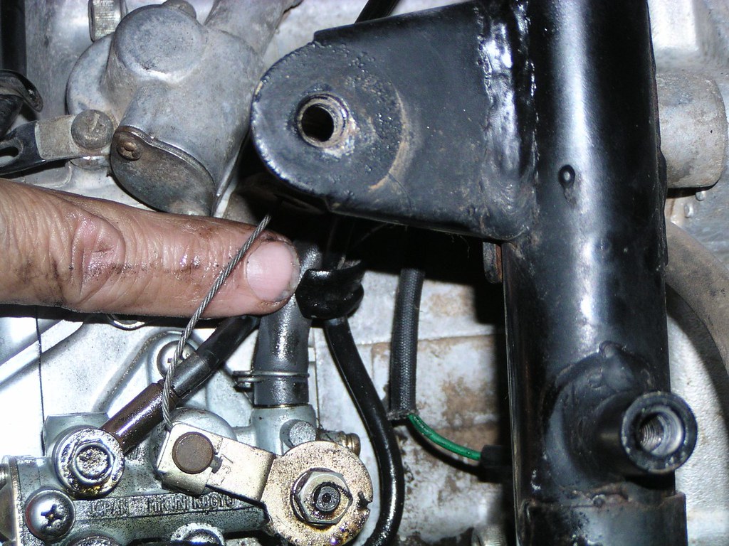
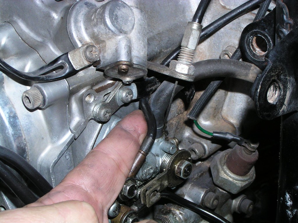
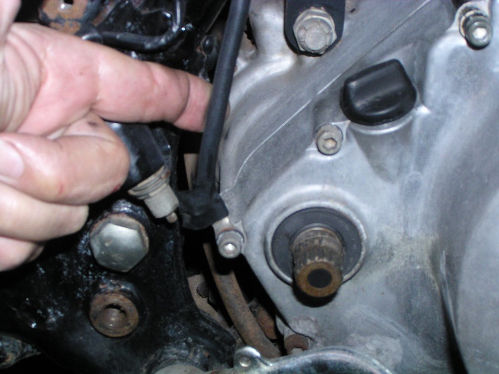
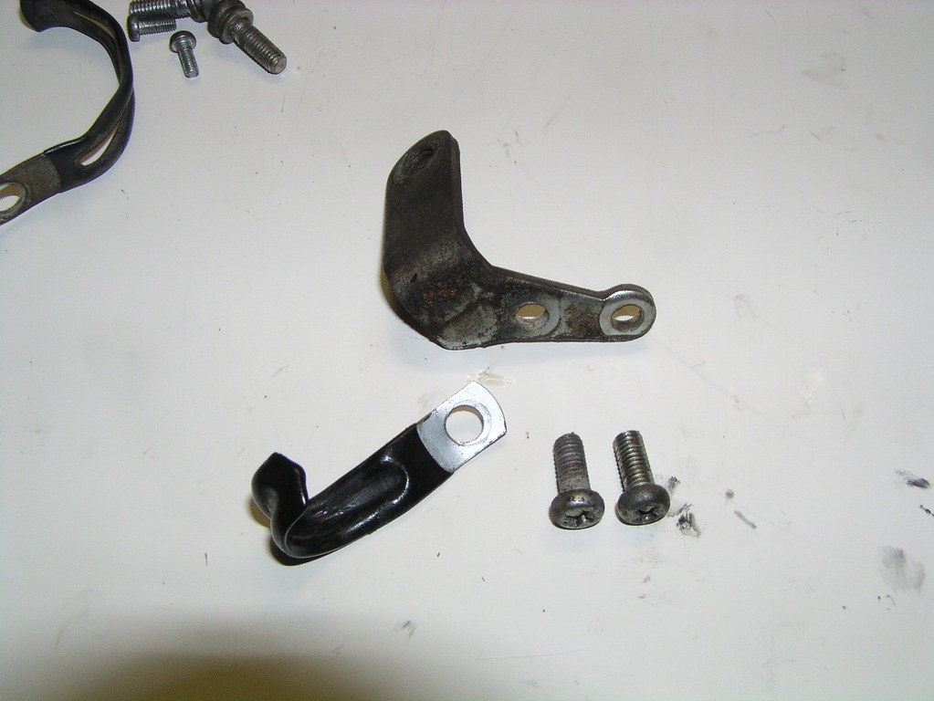
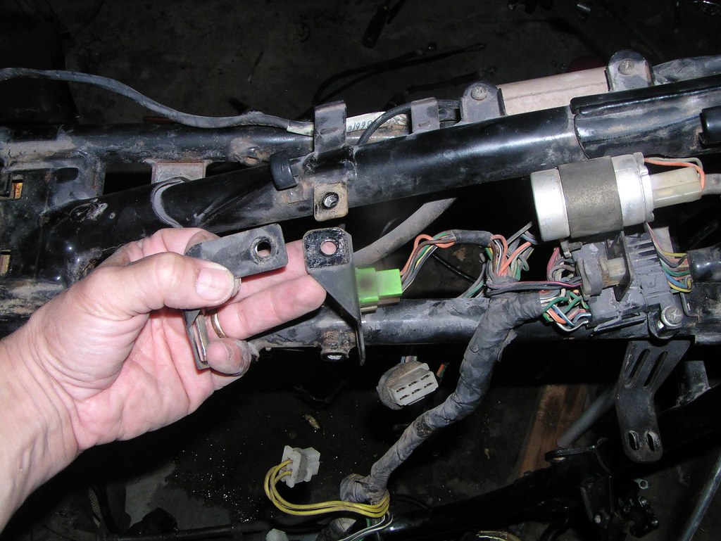
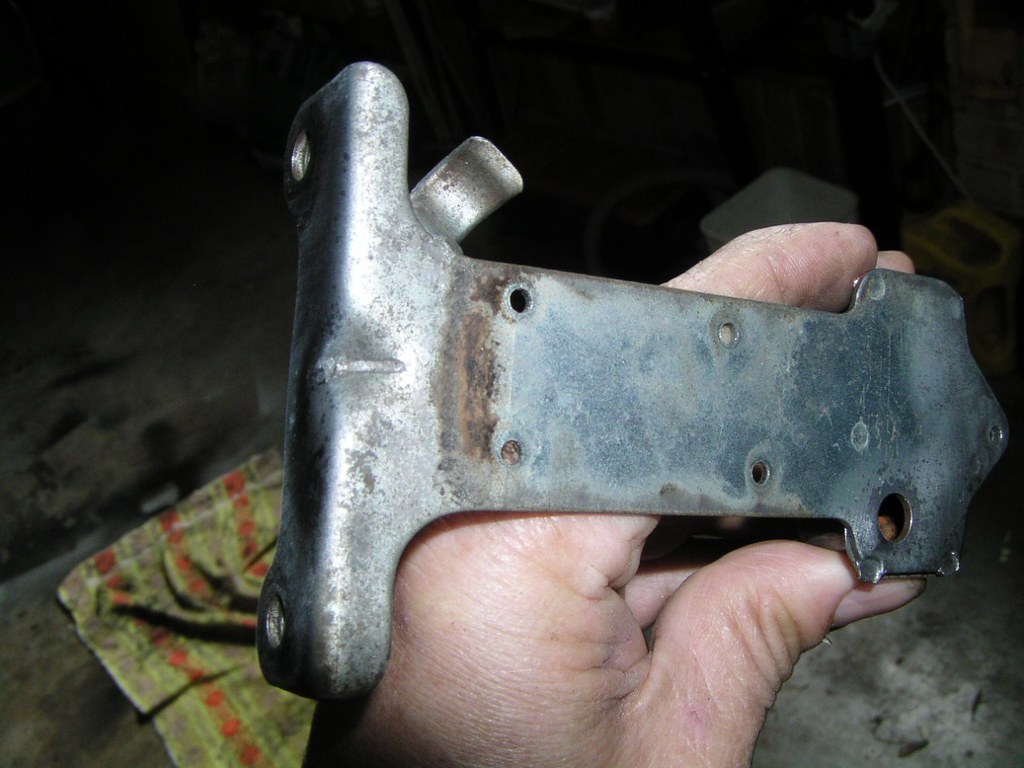
Where my middle finger is resting is the st*d that holds this particular br*cket on the inl*t manif*ld
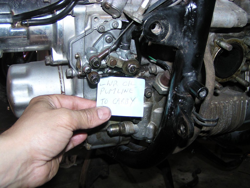
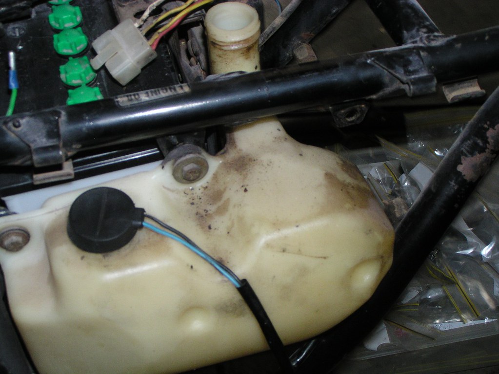
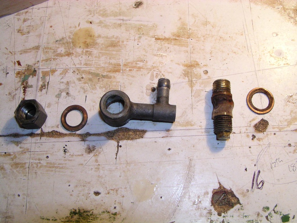
This is the fe*d line from the und*r-se*t o*l t*nk (meter*ng p*mp supply)
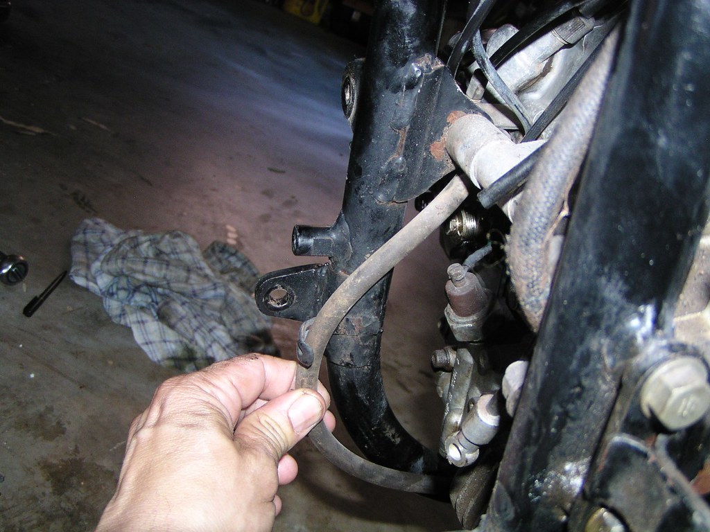
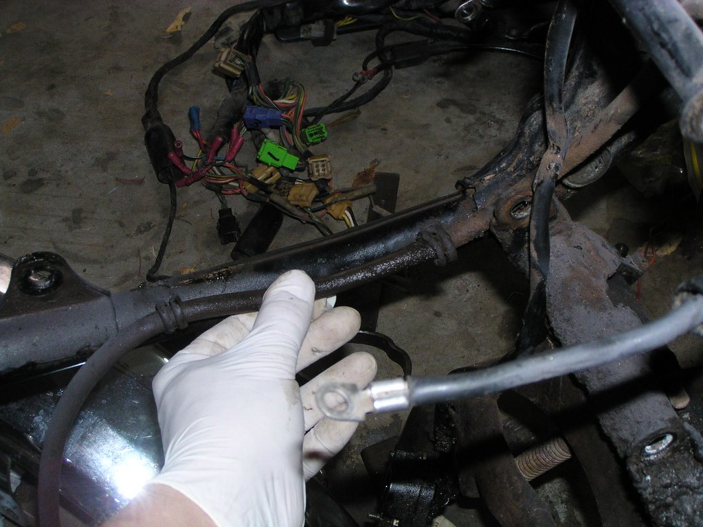
This is taken from the left side of the bike looking diagonally forward with the O*l t*nk itself removed
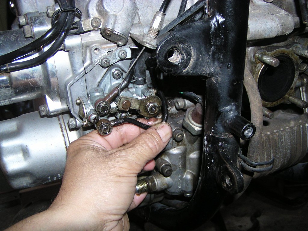
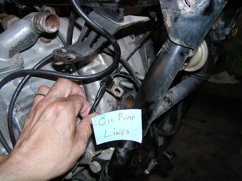
This is the cha*n oil*r l*ne, the upper of the two outp*t p*pes from the meter*ng p*mp
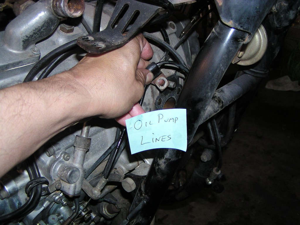
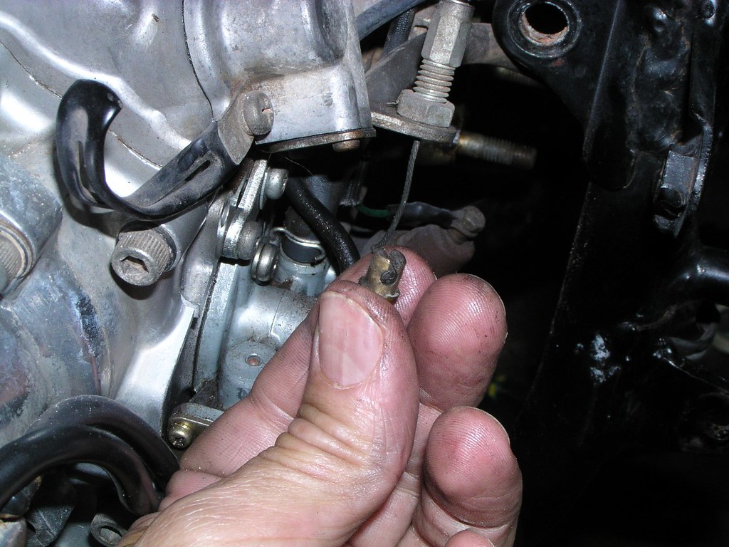
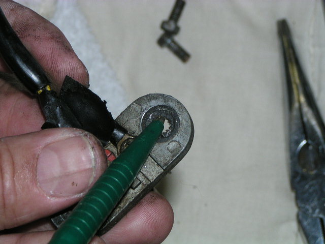
Disconnecting the c*ble that operates the o*l fl*w contr*l ar*m on the meter*ng p*mp. You'll be wondering where this particular little br*ss thingy belongs a year from now during reassembly
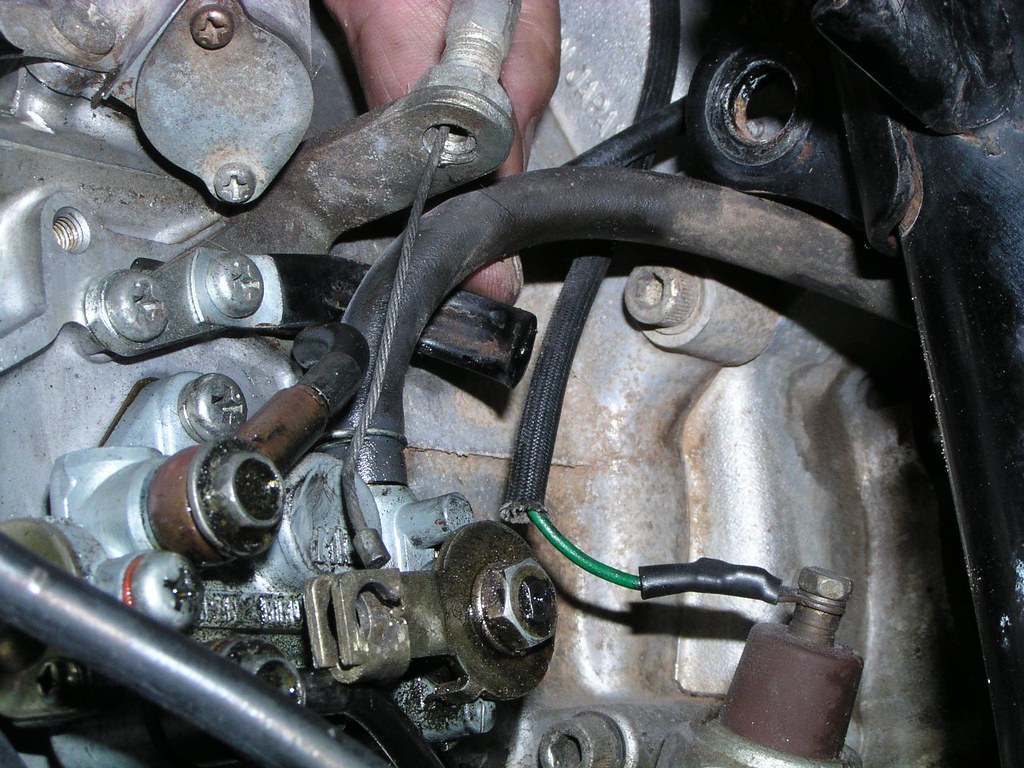
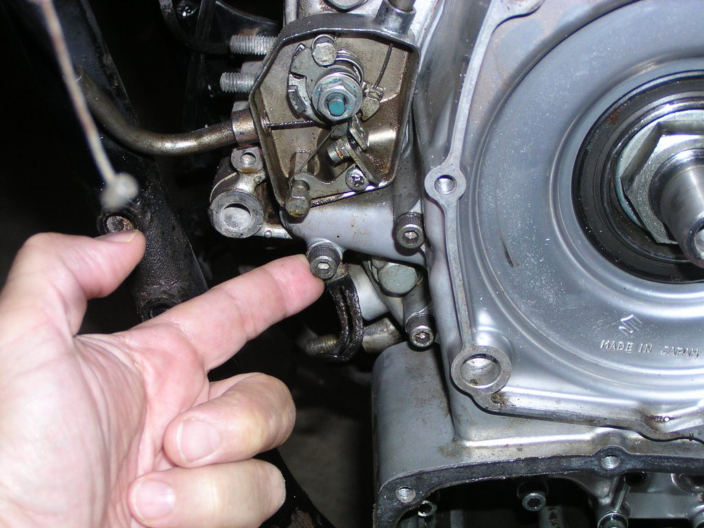
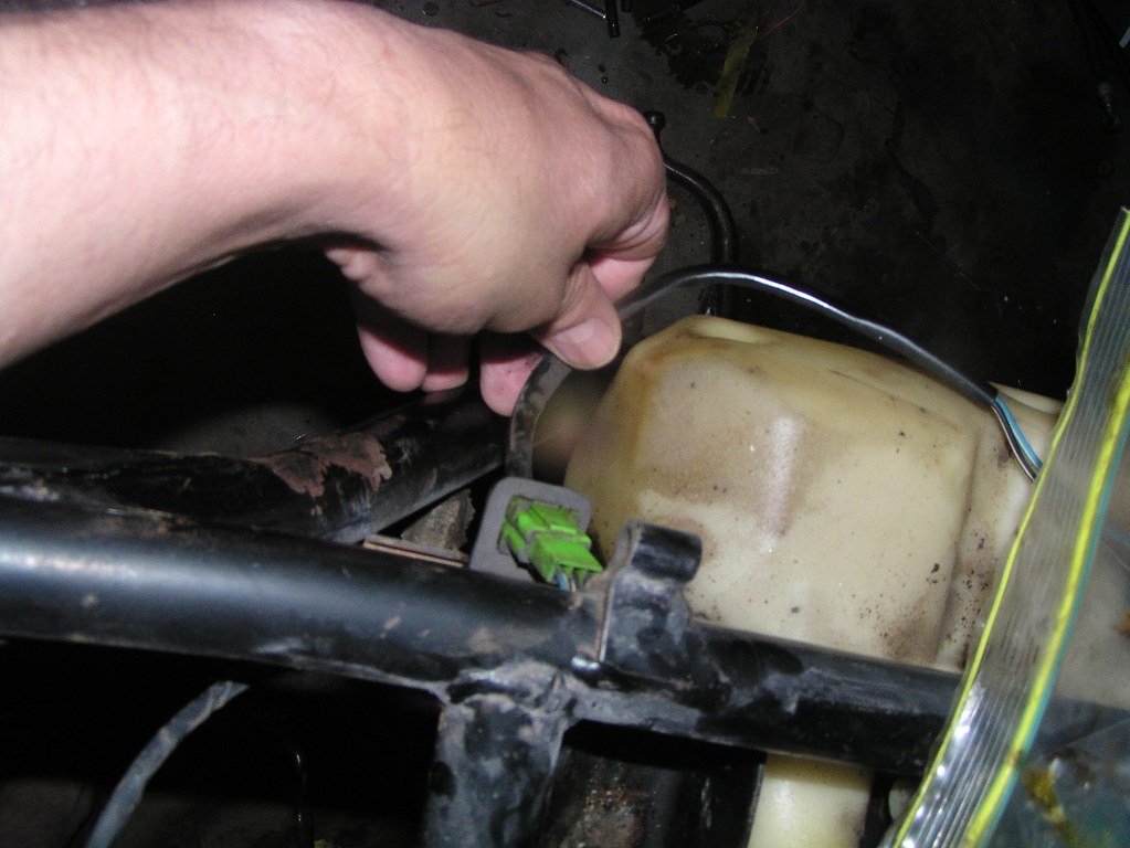
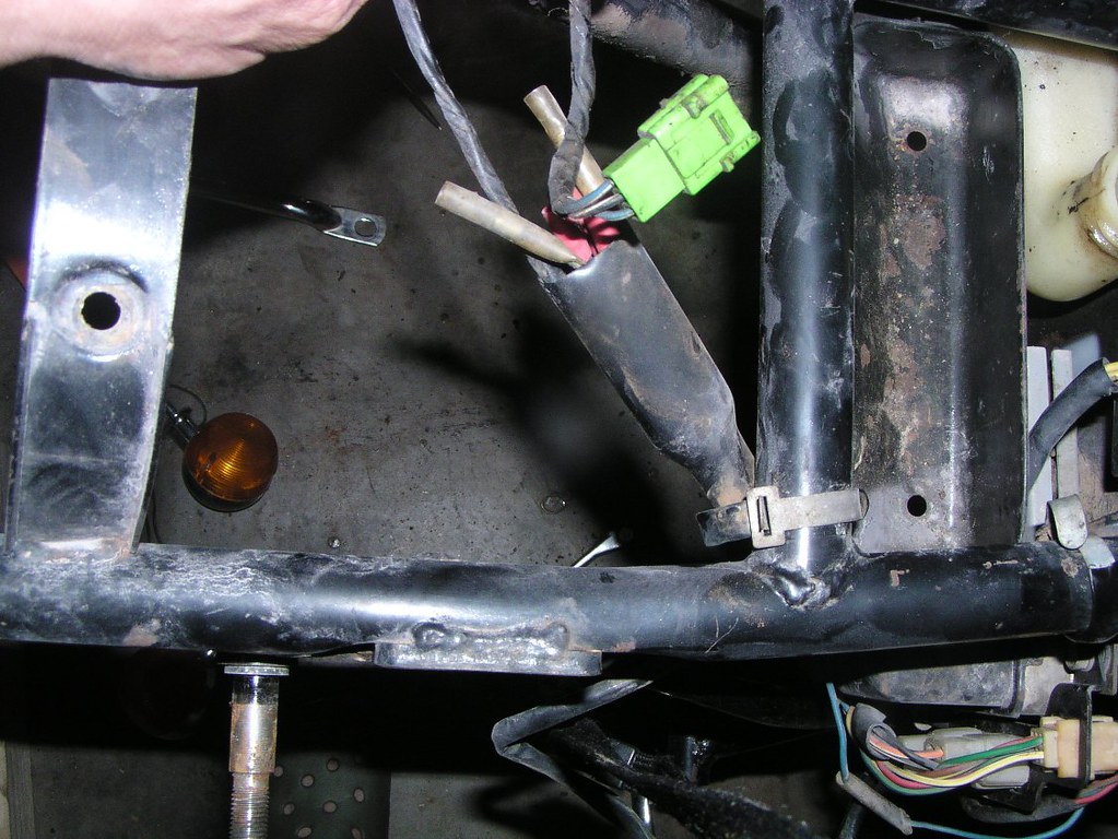
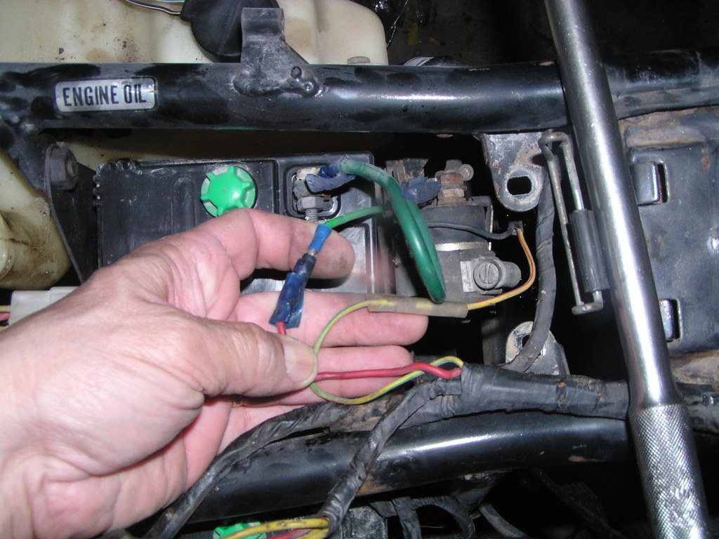
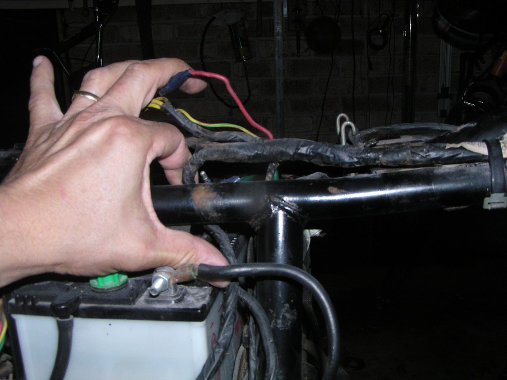
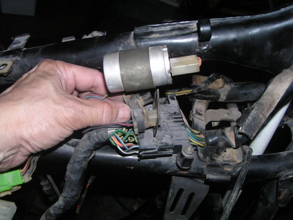
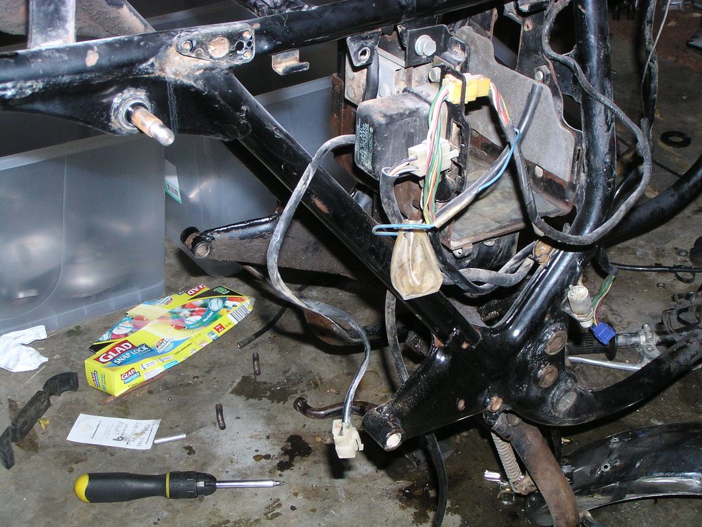
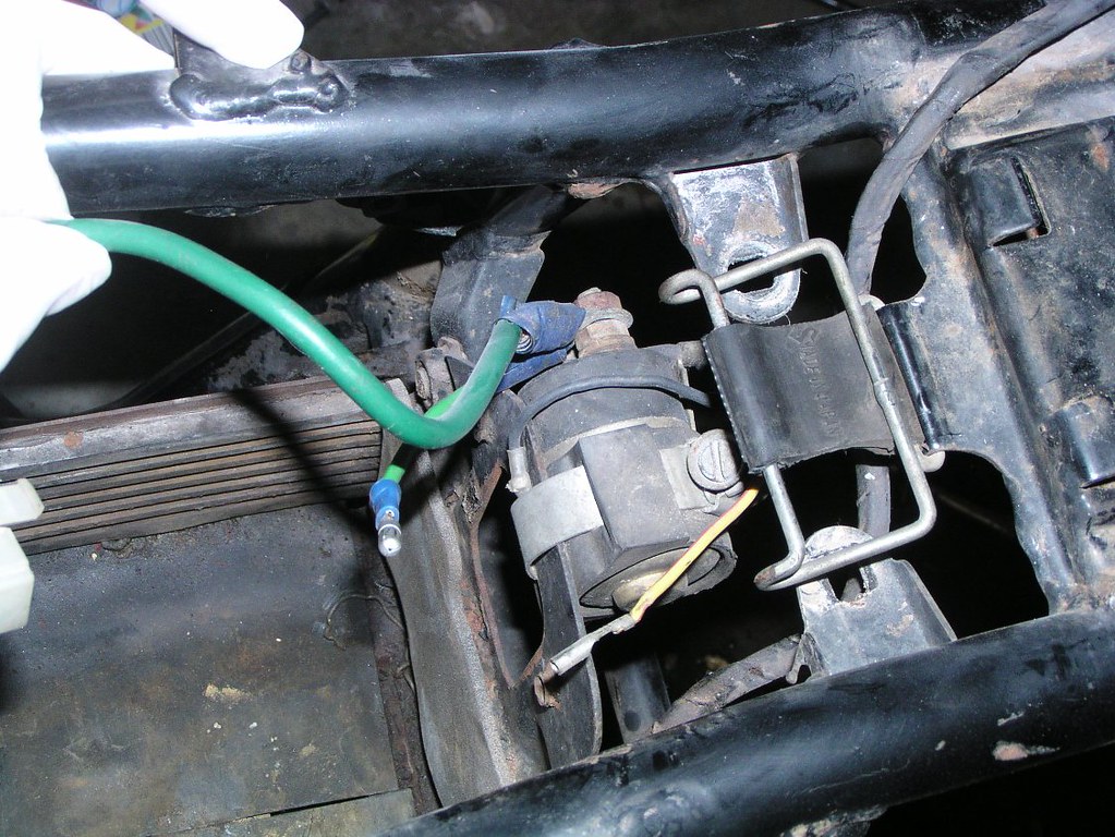
For reference, the green w*re in the photo below is connected to the o*l press*re swit*h (lower front right of eng*ne
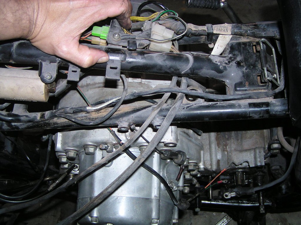
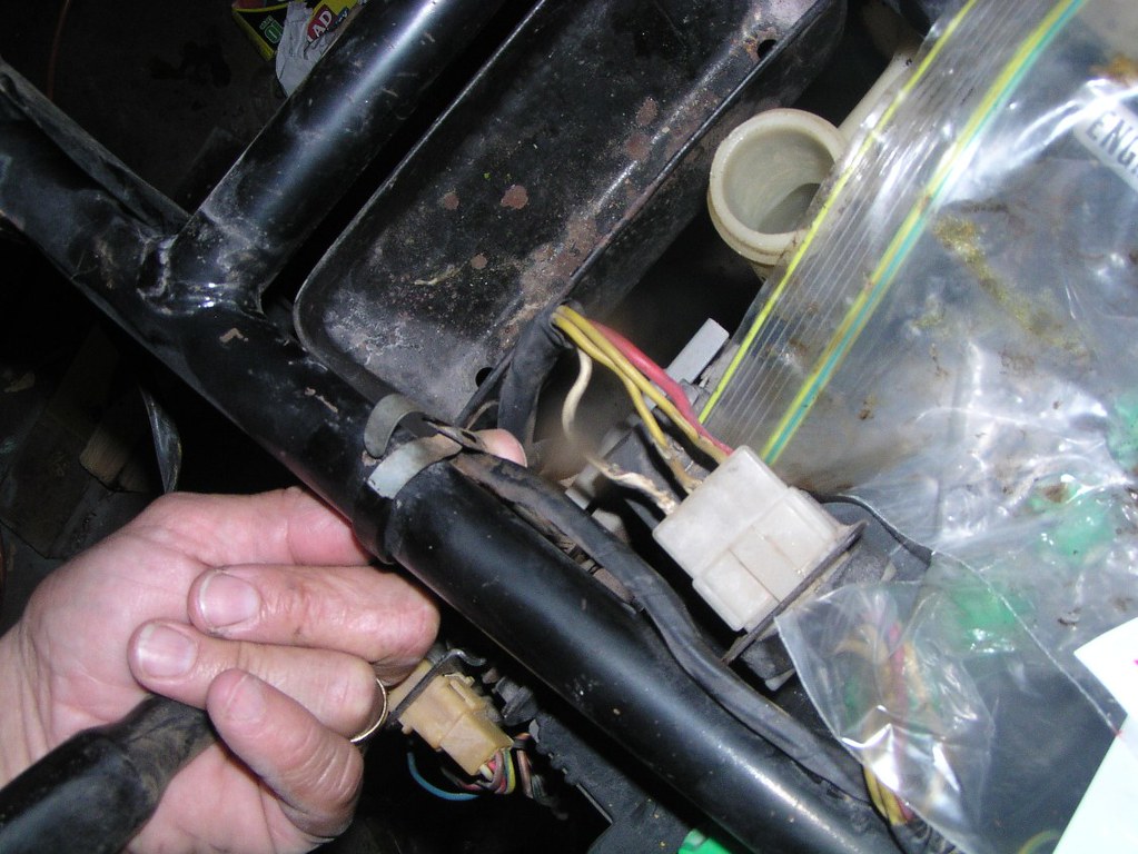
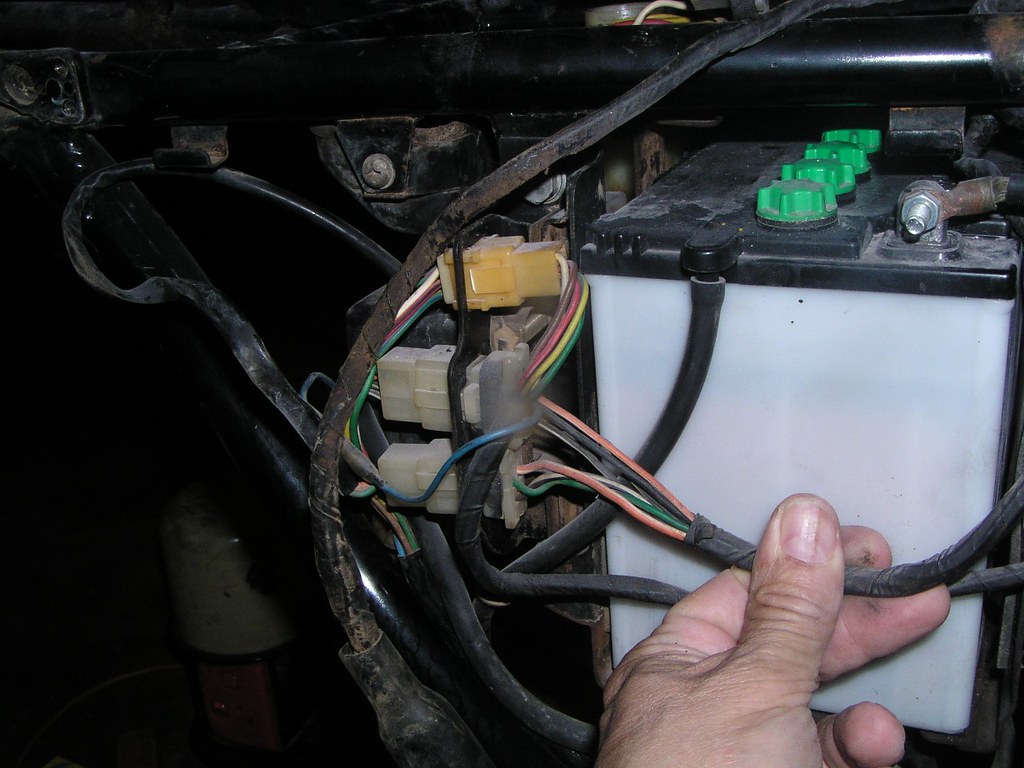
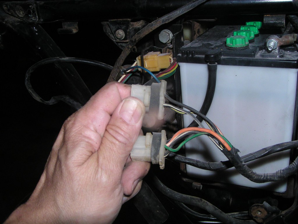
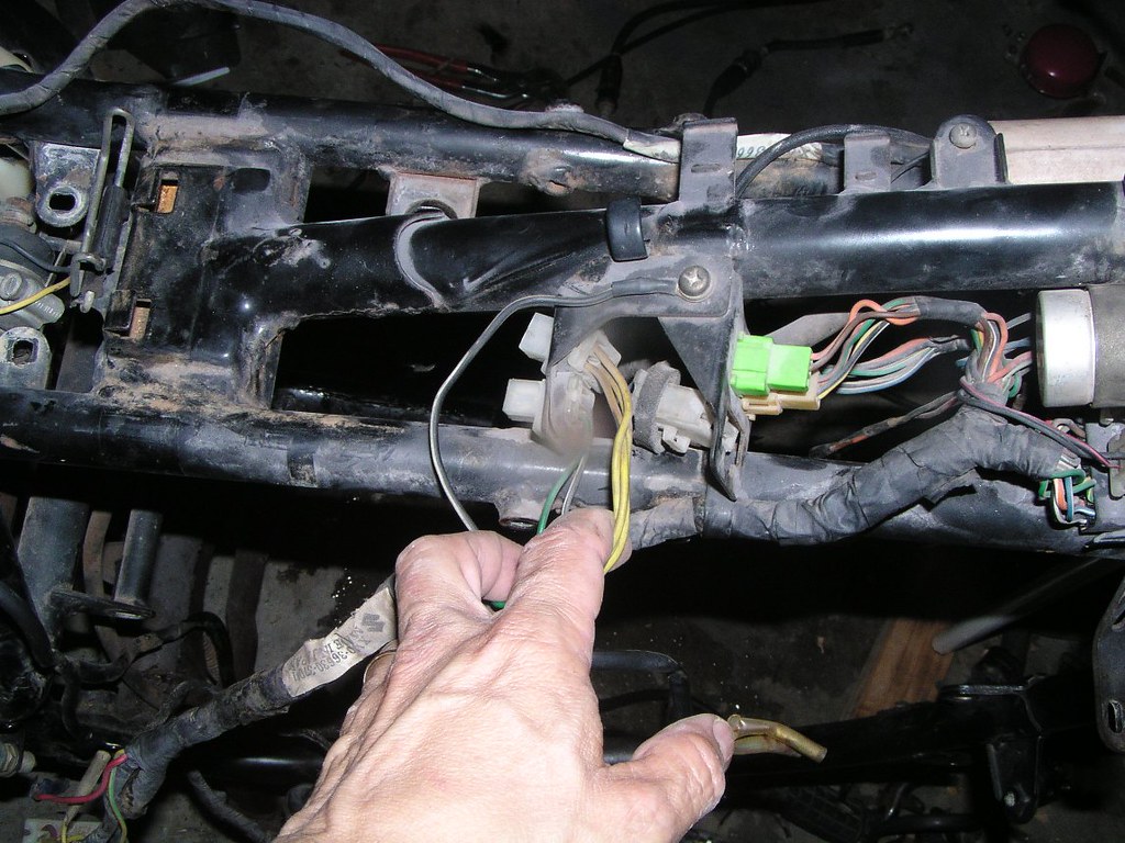
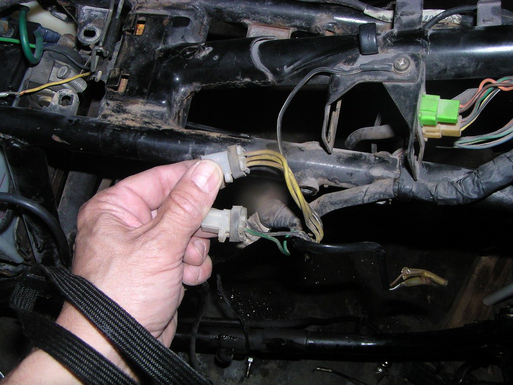
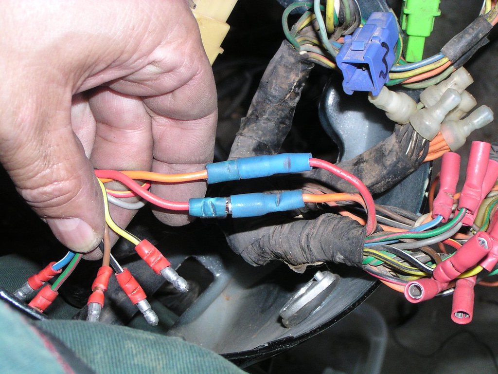
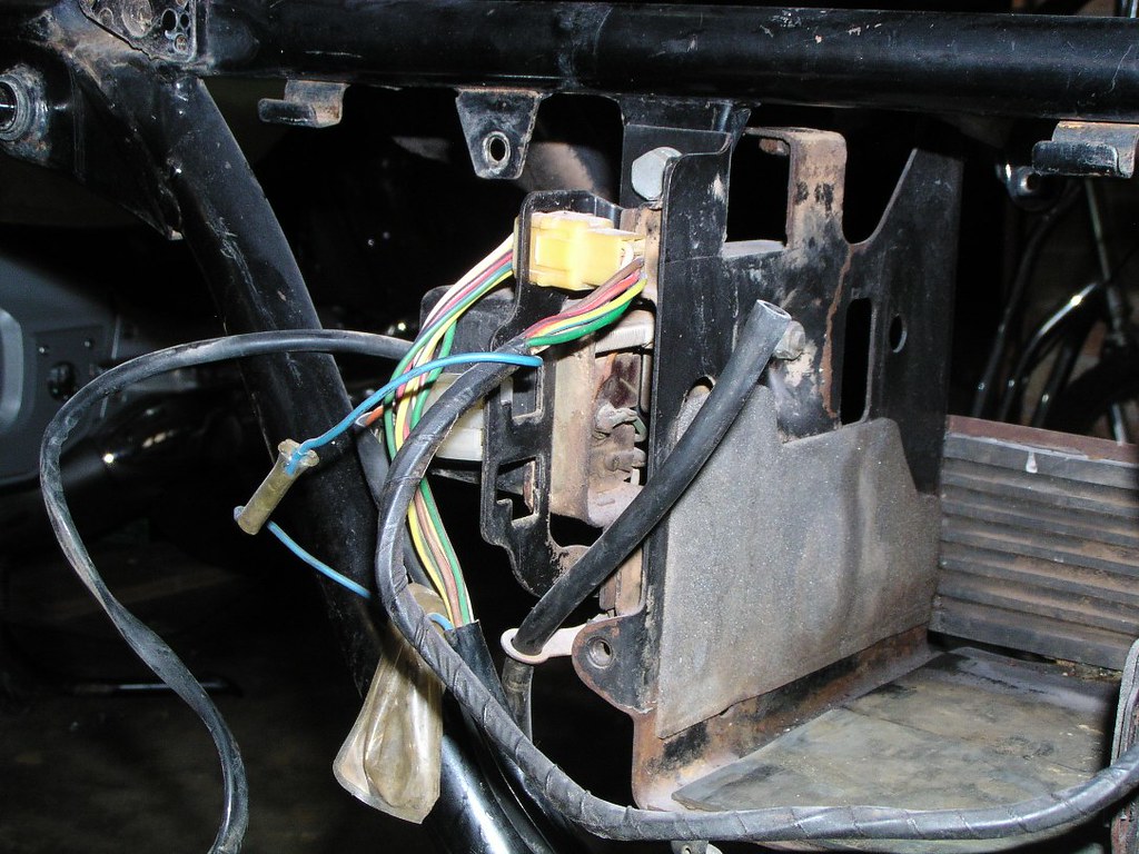
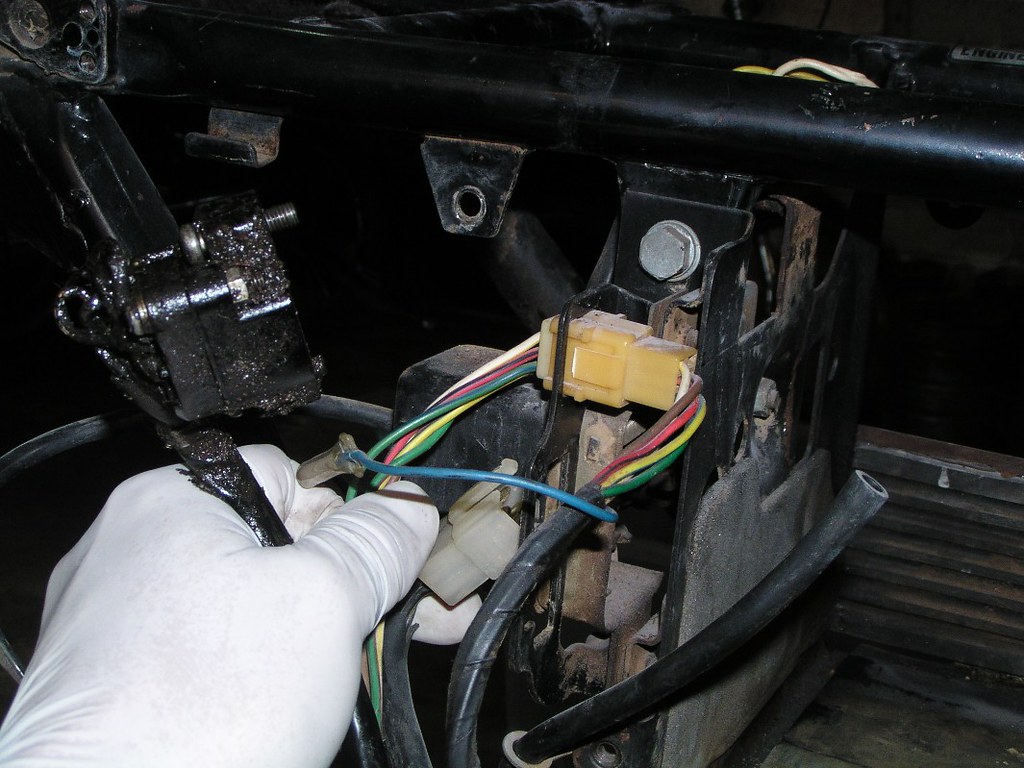
Now we trace the Alt*rnator wir*ng st*rting from the sw*tchbl*cks under the f*el t*nk
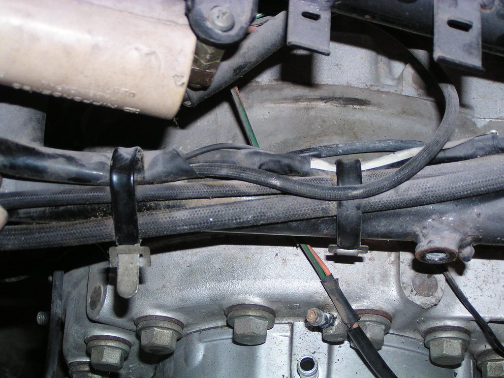
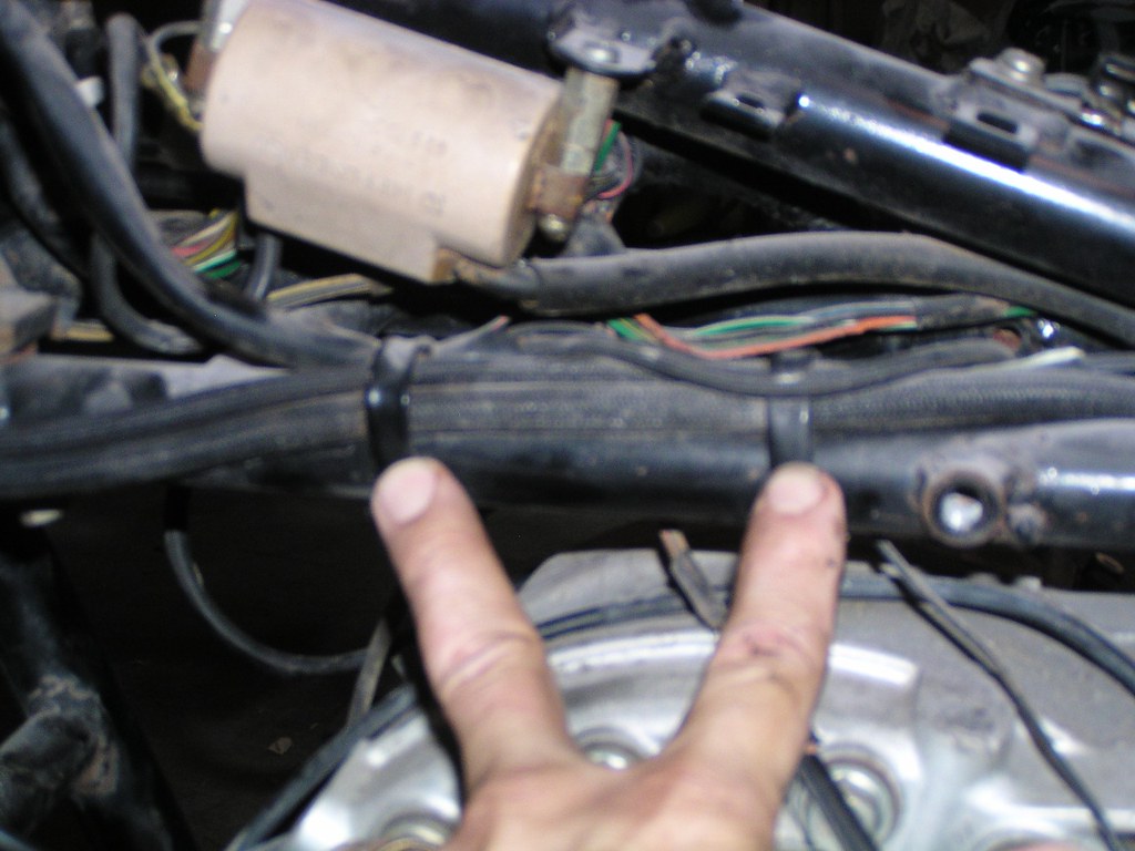
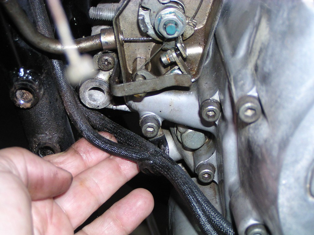
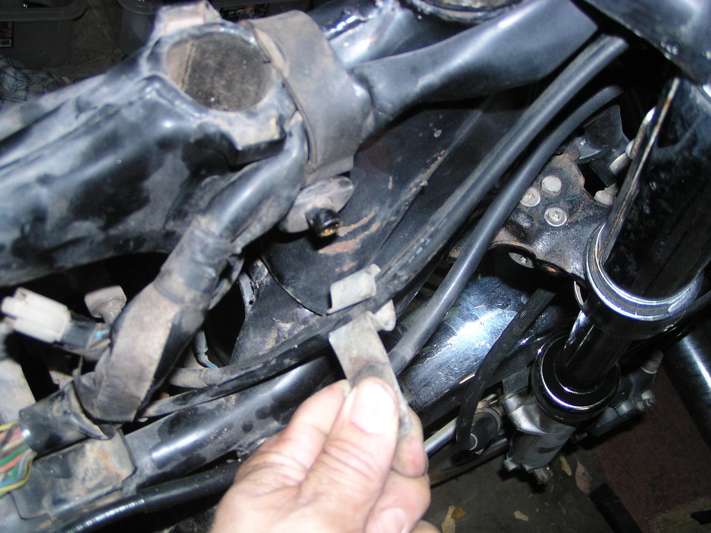
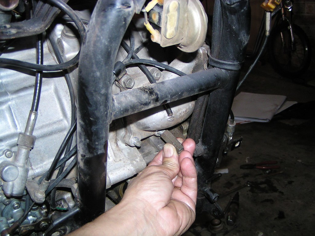
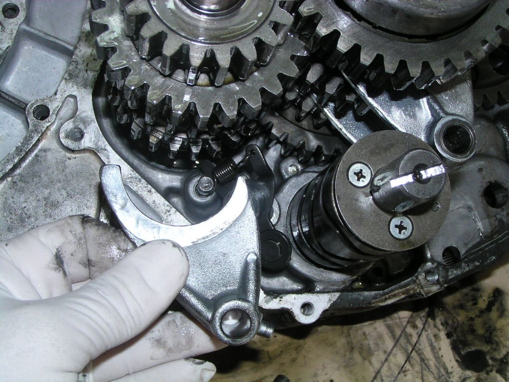
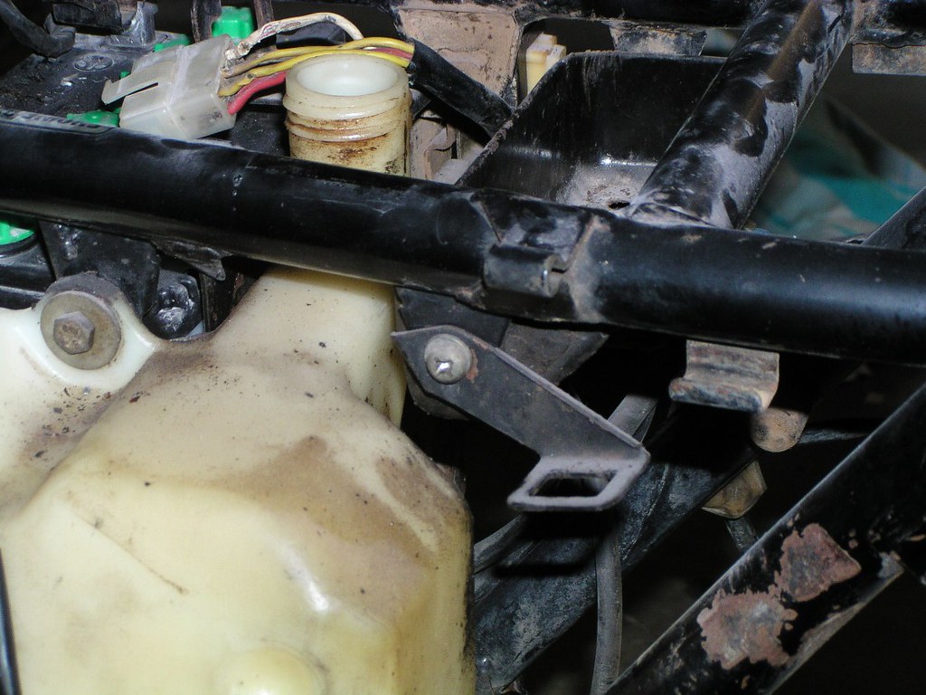
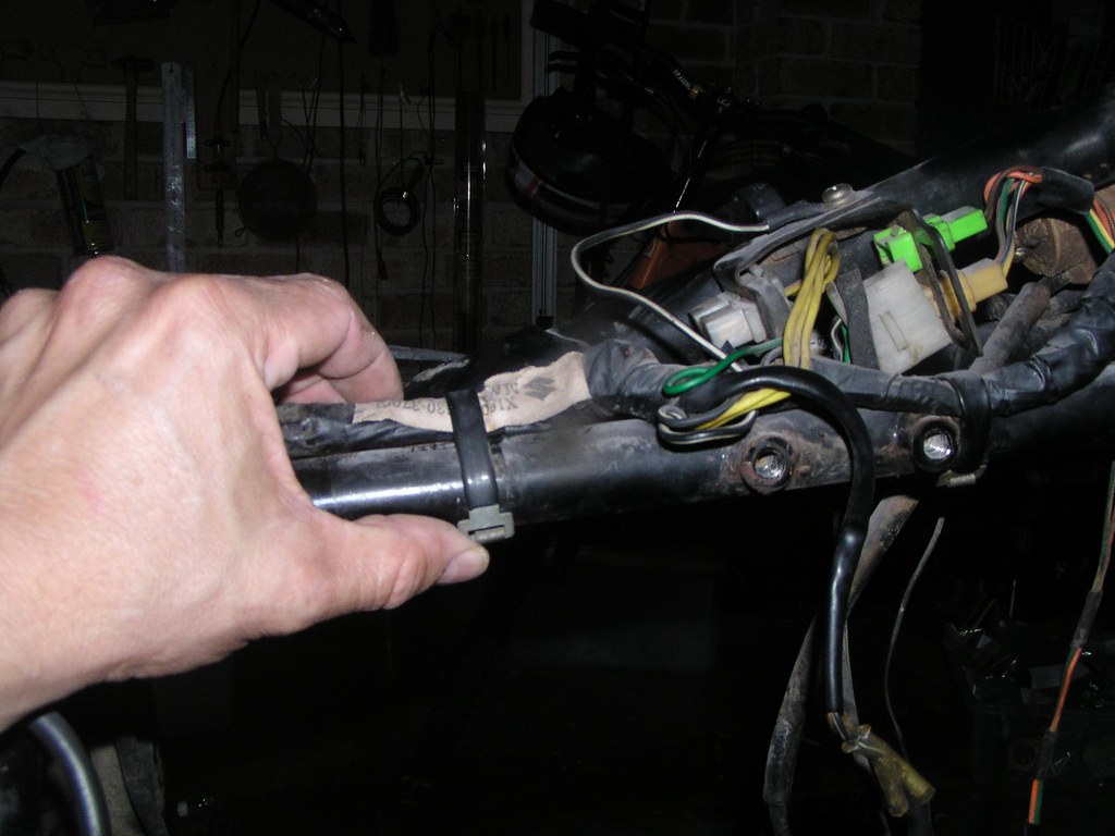
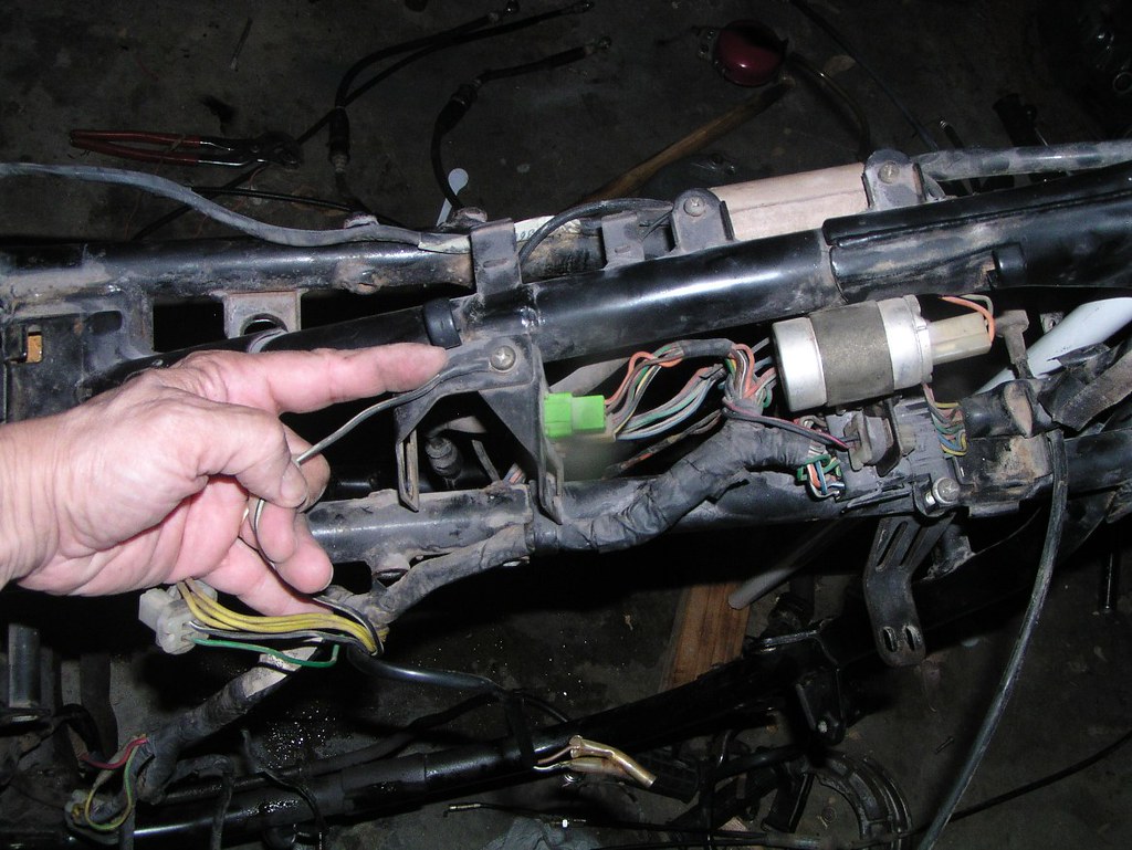
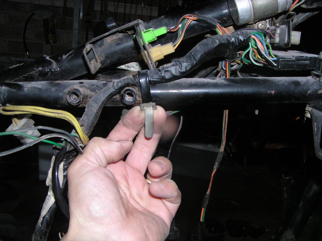
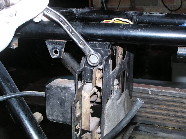
Note the location of this small c*ble str*p fitted below the P*rt V*lve h*using
]
]

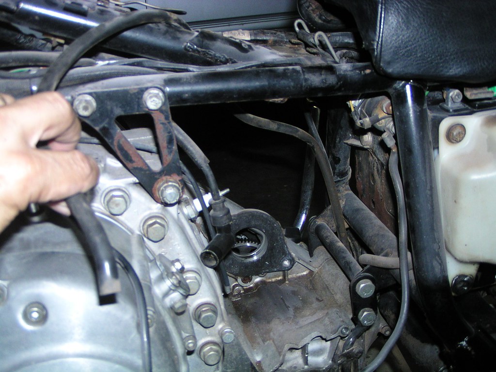
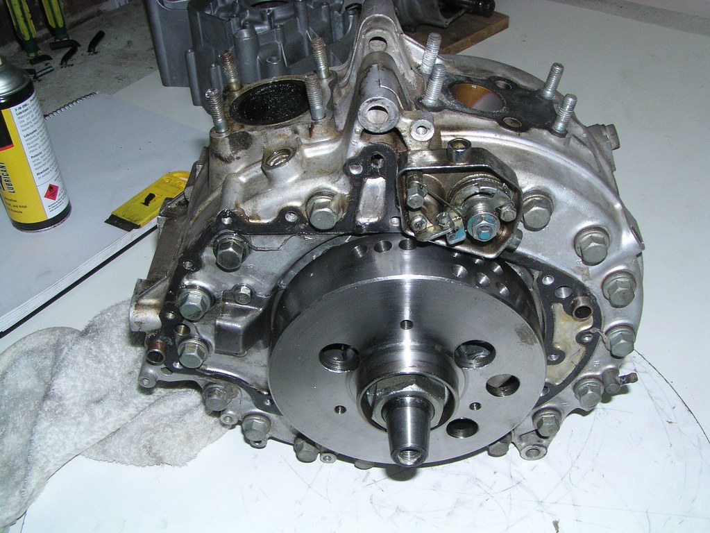
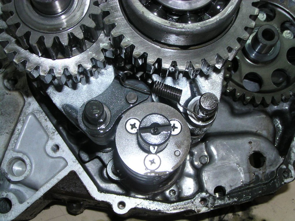
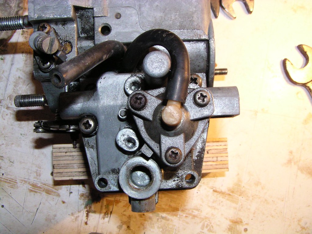
Detail photo of the p*rt valve h*using. NOTE: you do not have to remove any of this mechanism, only disconnect the c*bles. The pr*per un*t and p*rt valve ho*sing stay together, even a new pr*per un*t already has this in place.
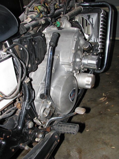
General view of the left side of the eng*ne with the count*rweight c*ver now removed
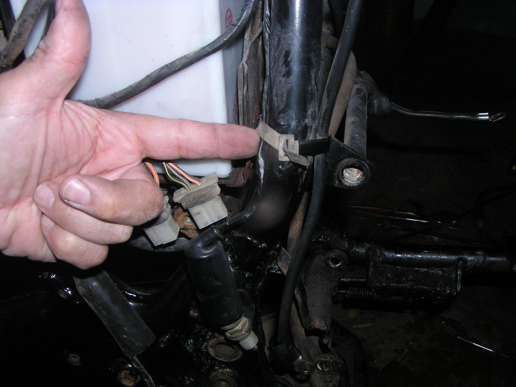
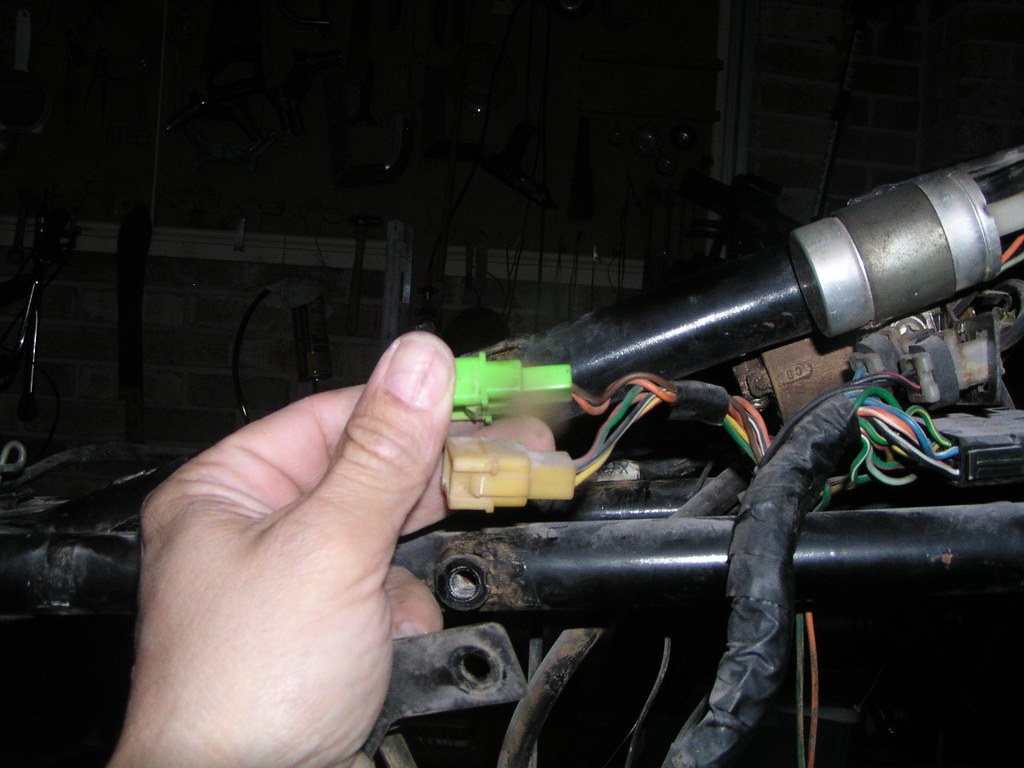
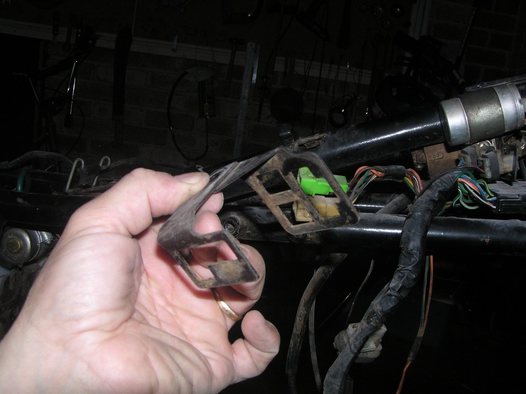
Generally speaking, the earlier models had met*l br*ckets holding many of these pl*gs. The later models did not. It's possible that even a '76 A model may have these br*ckets, if so, it probably just means that it's a conv*rted early M that languished on some dealership's floor for too long.
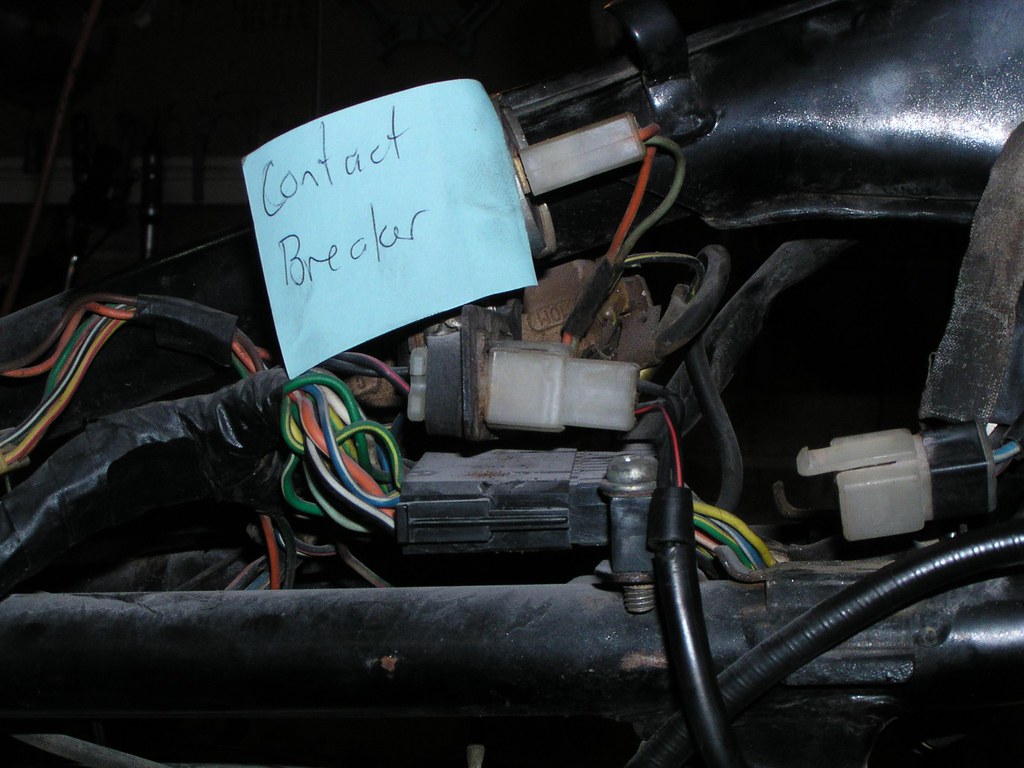
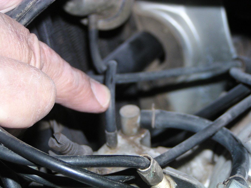
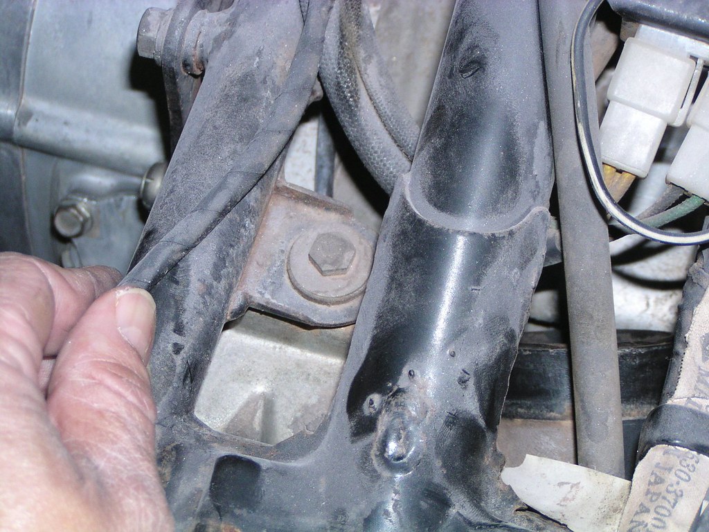
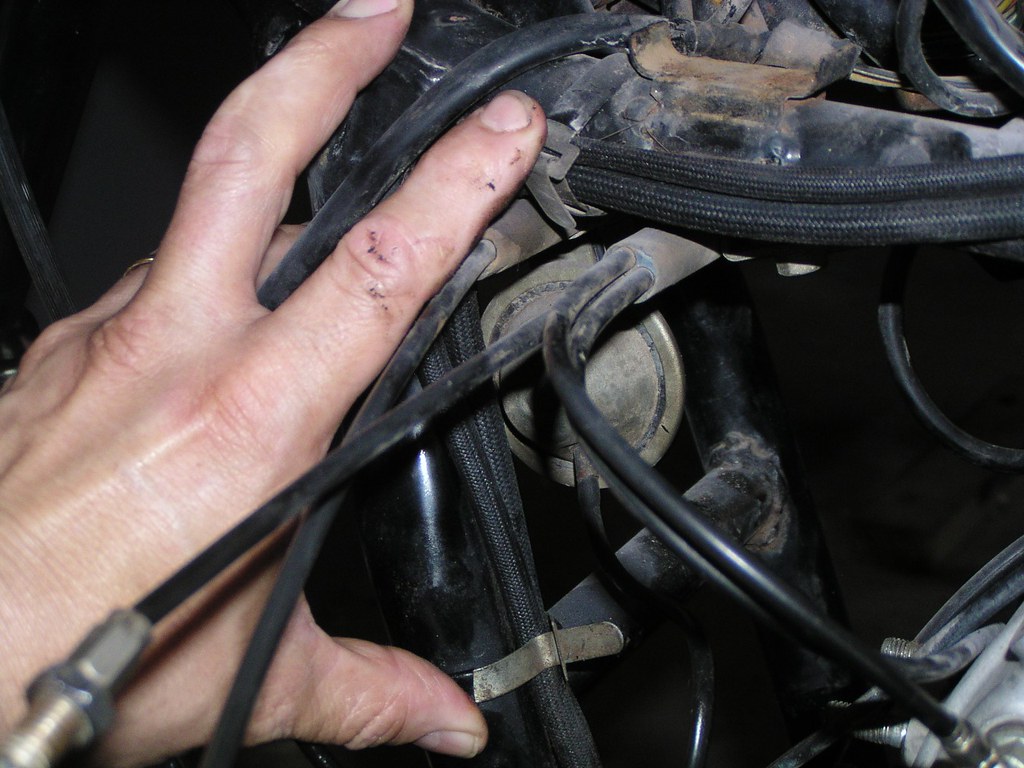
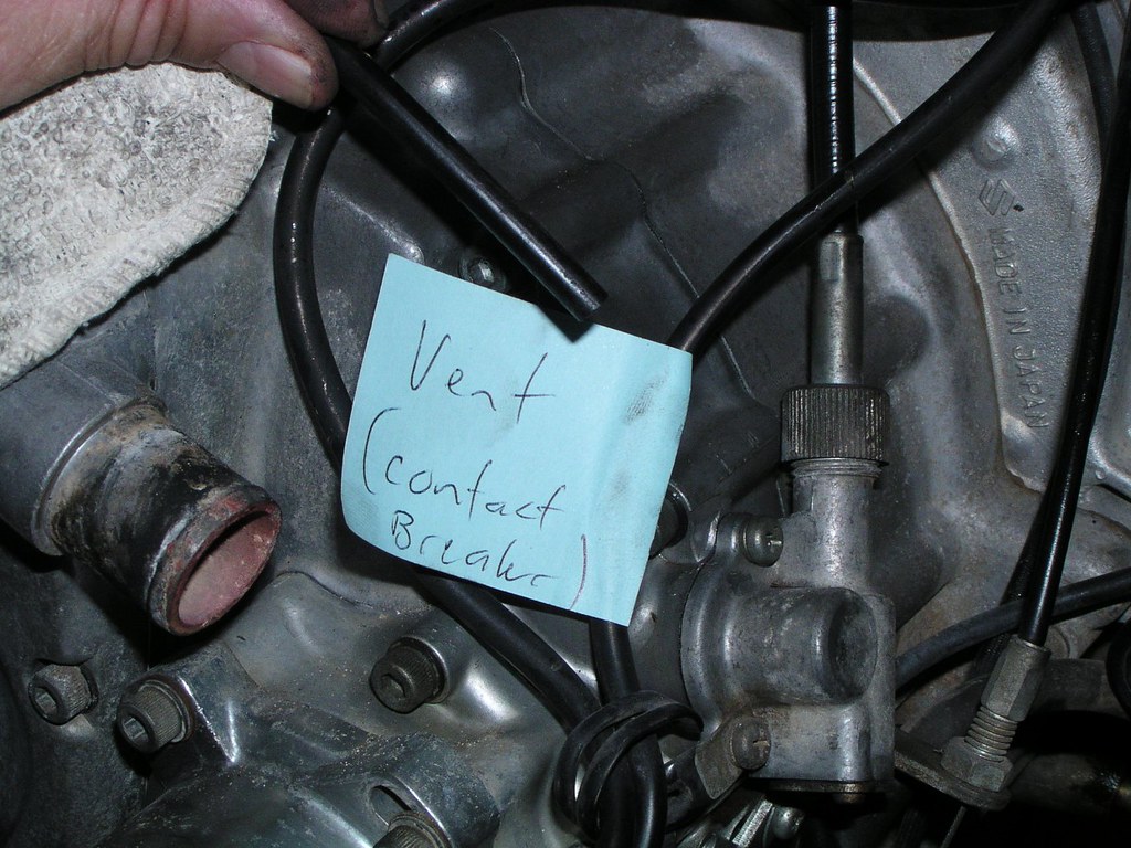
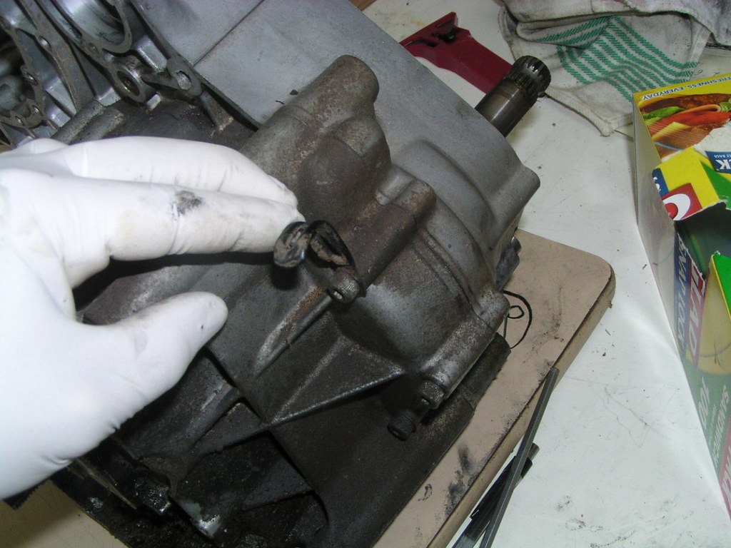
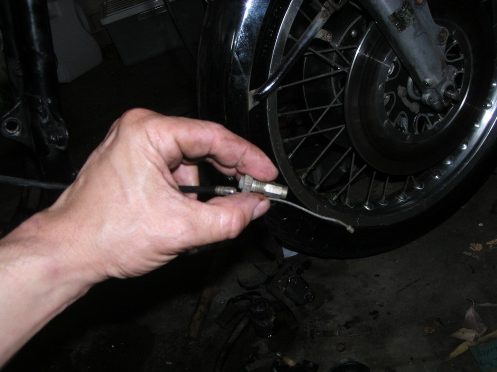
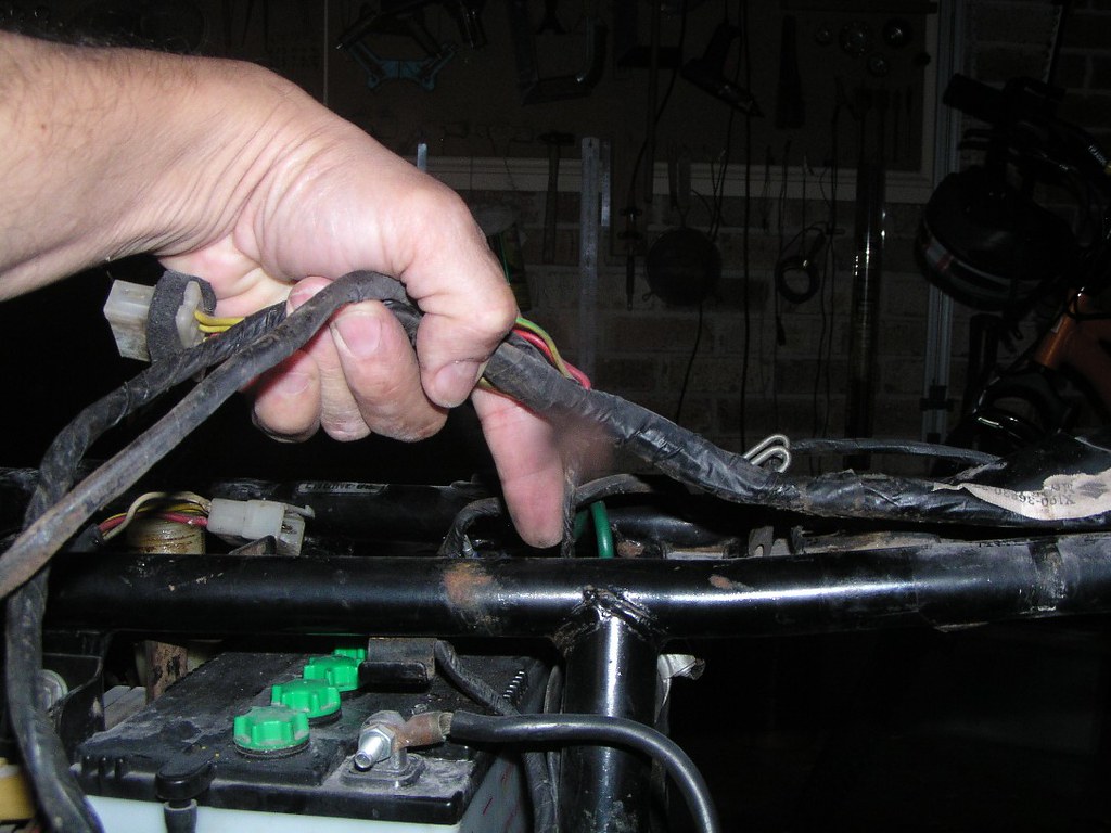
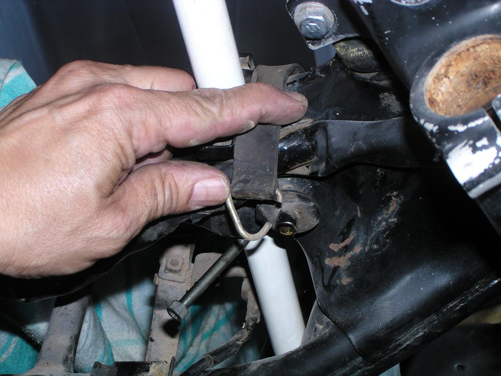
The other t*be exiting the bre*ker ho*sing doesn't go anywhere in particular (the one below the w*re I'm touching). It's just a bre*ther and usually is just routed up under the t*nk and secured by one of the wir*ng cl*mps.
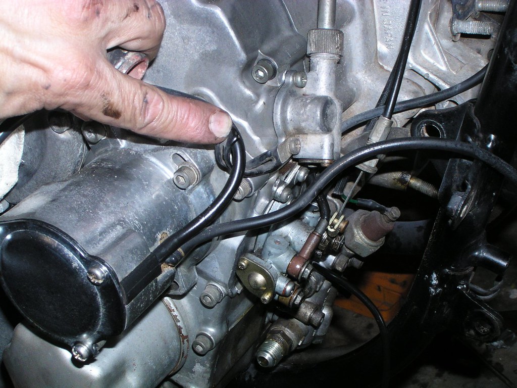
This is the end of the bre*ker ho*sing bre*ther that normally is just secured under the t*nk. Leave it open.
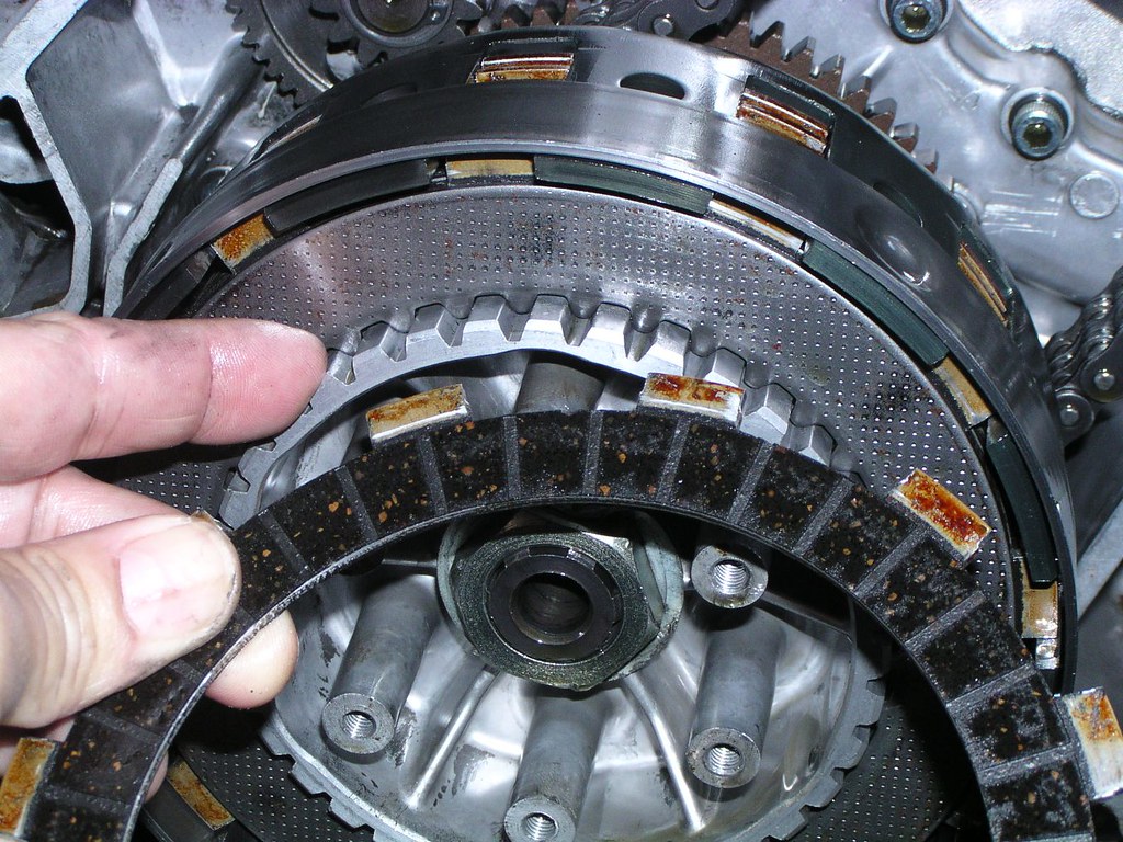
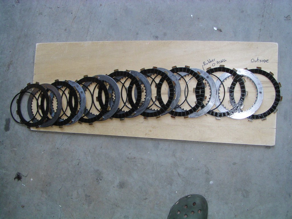
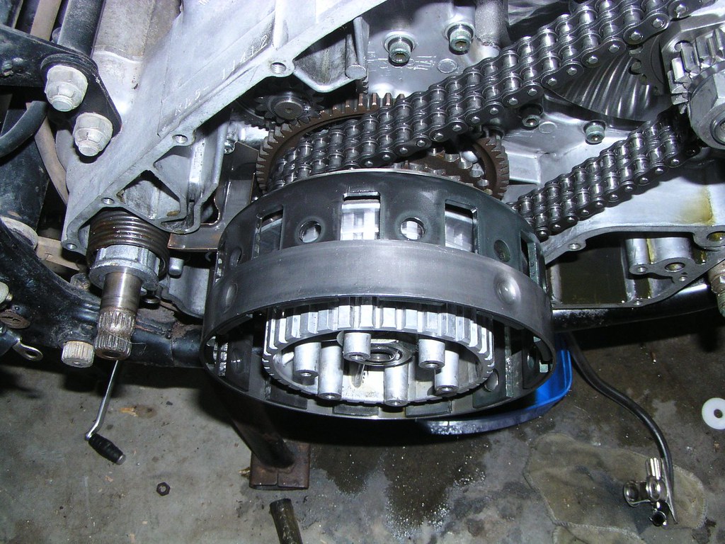
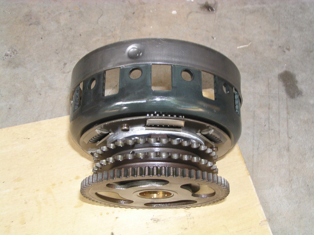
K*ckst*rt, Cl*tch c*ver, cl*tch and prim*ry dr*ve disassembly
E*rthwire (neg*tive) from the batt*ry is normally secured to this b*lt on the cl*tch c*ver
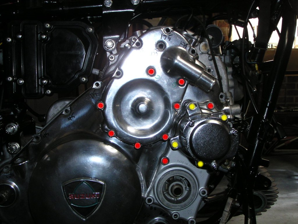
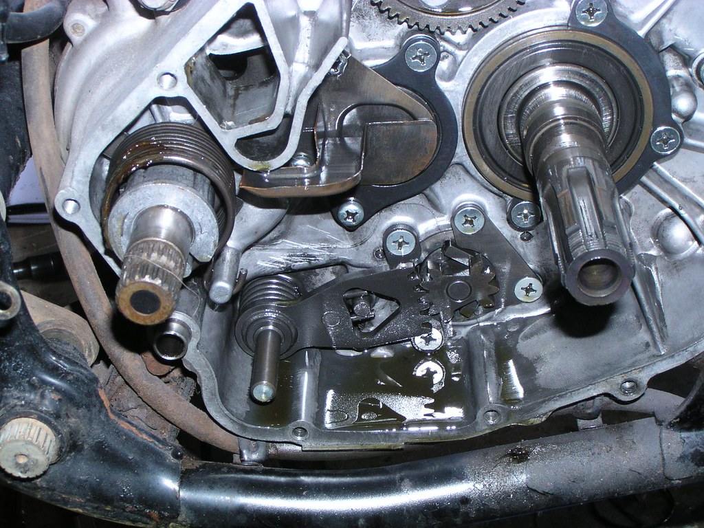
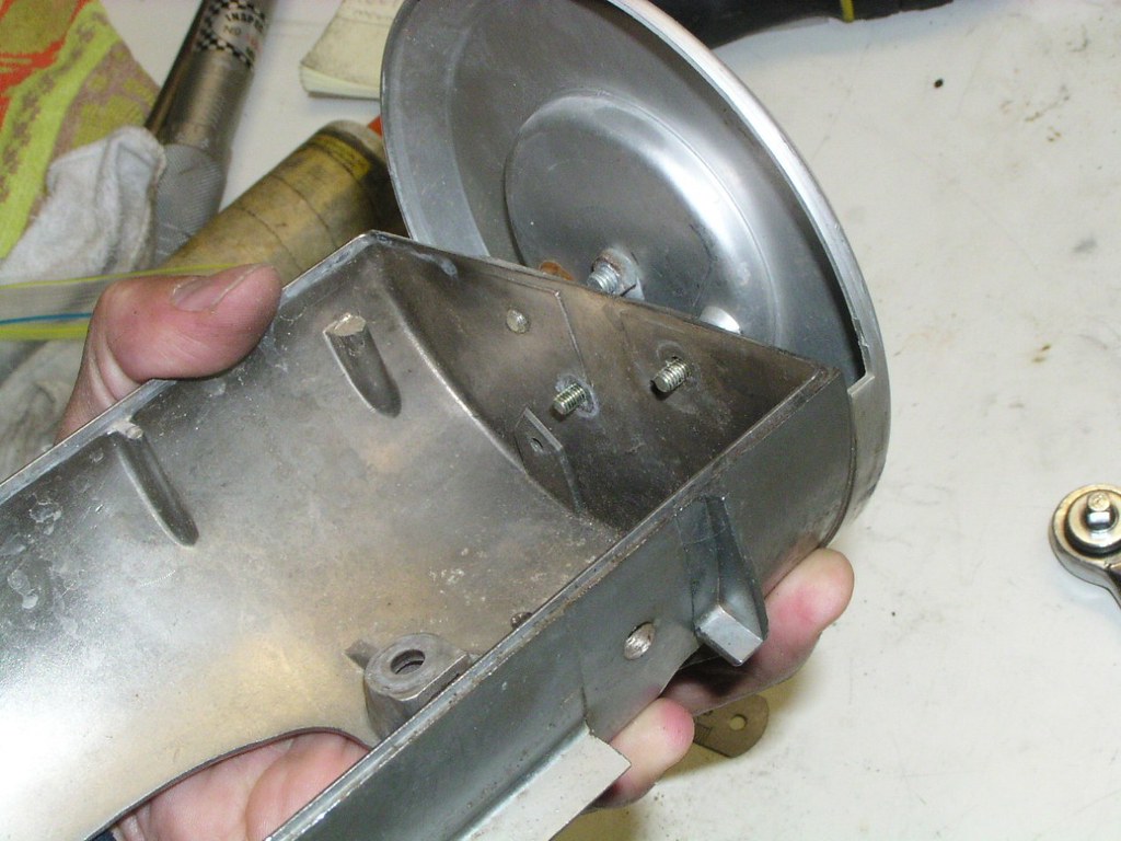
Make sure you remove all the b*lts holding the cl*tch cover to the frame mounted eng*ne cas*ng. The cov*r can be very difficult to remove even with all b*lts removed as the old gask*t "glues" it in place. Inadvertently having left one in could be disastrous if you try and force the cov*r off. The picture below shows the b*lts that you don't have to remove (but you may as well). These h*usings (wat*rpump, troch*id o*l p*mp and cont*ct bre*ker) can be removed later if you wish.
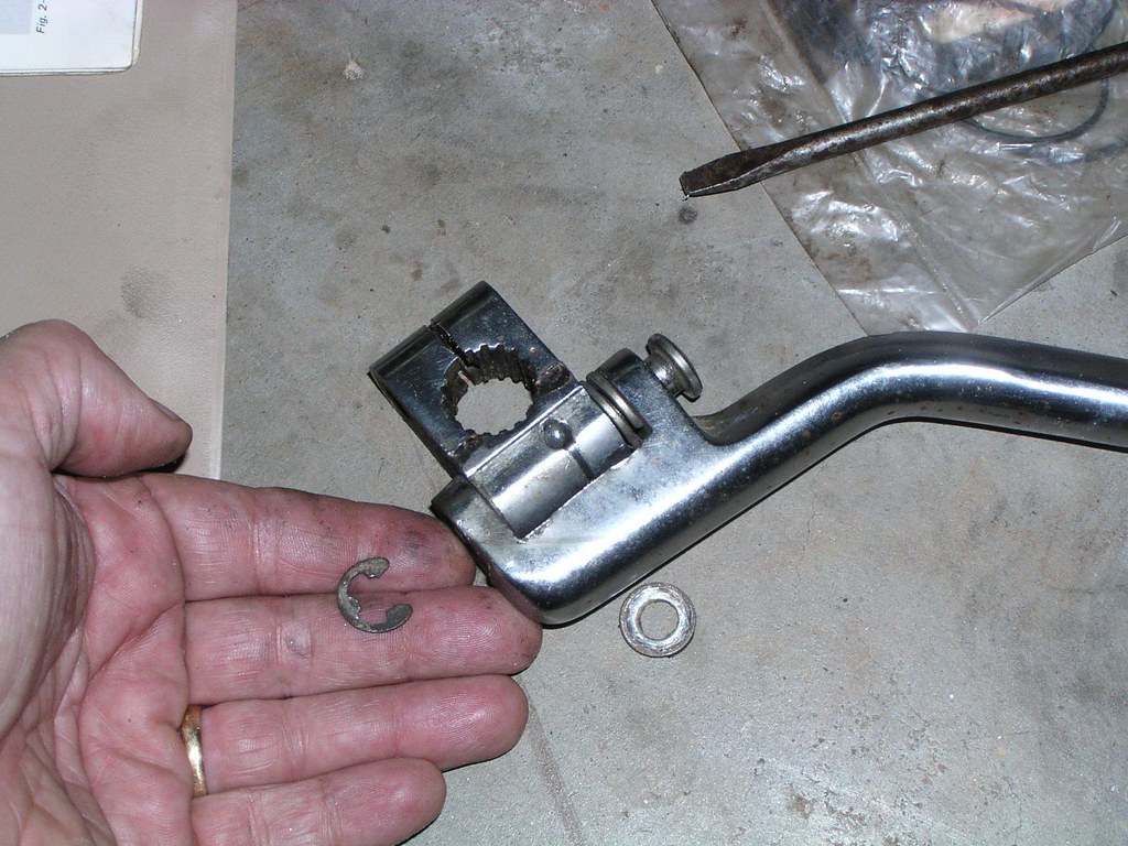
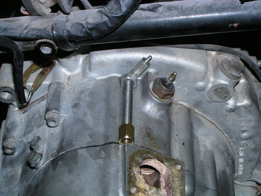
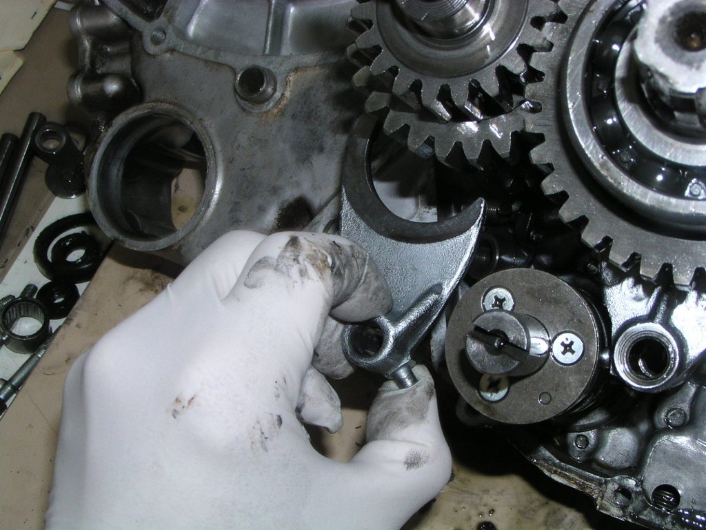
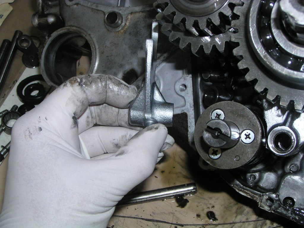
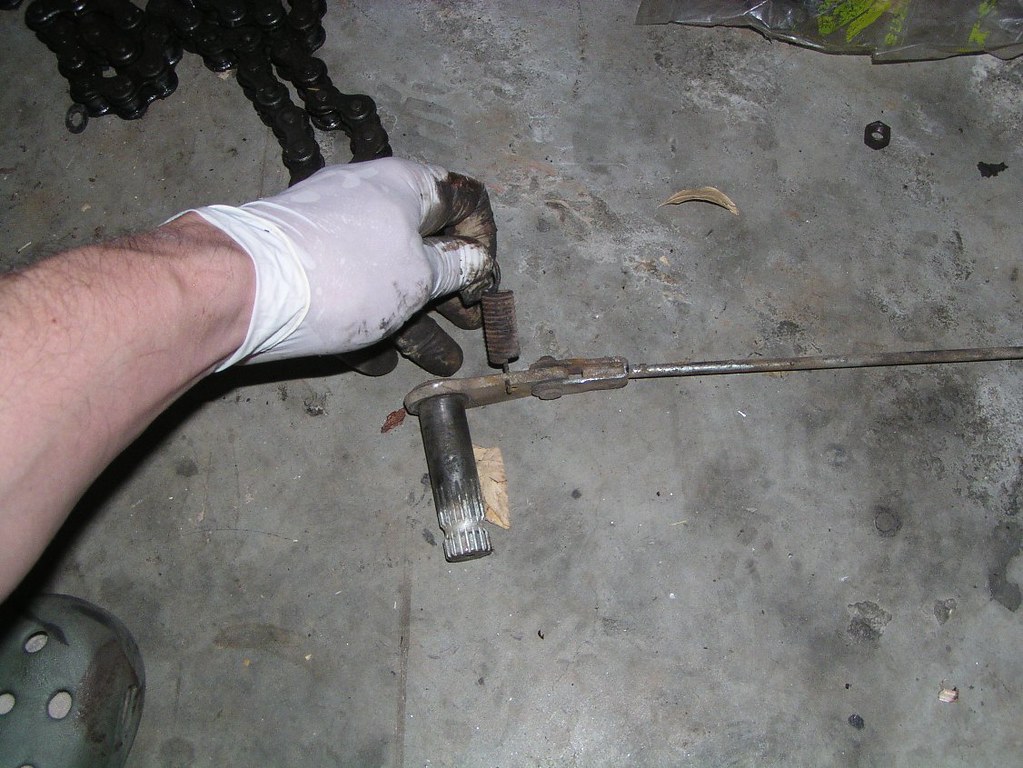
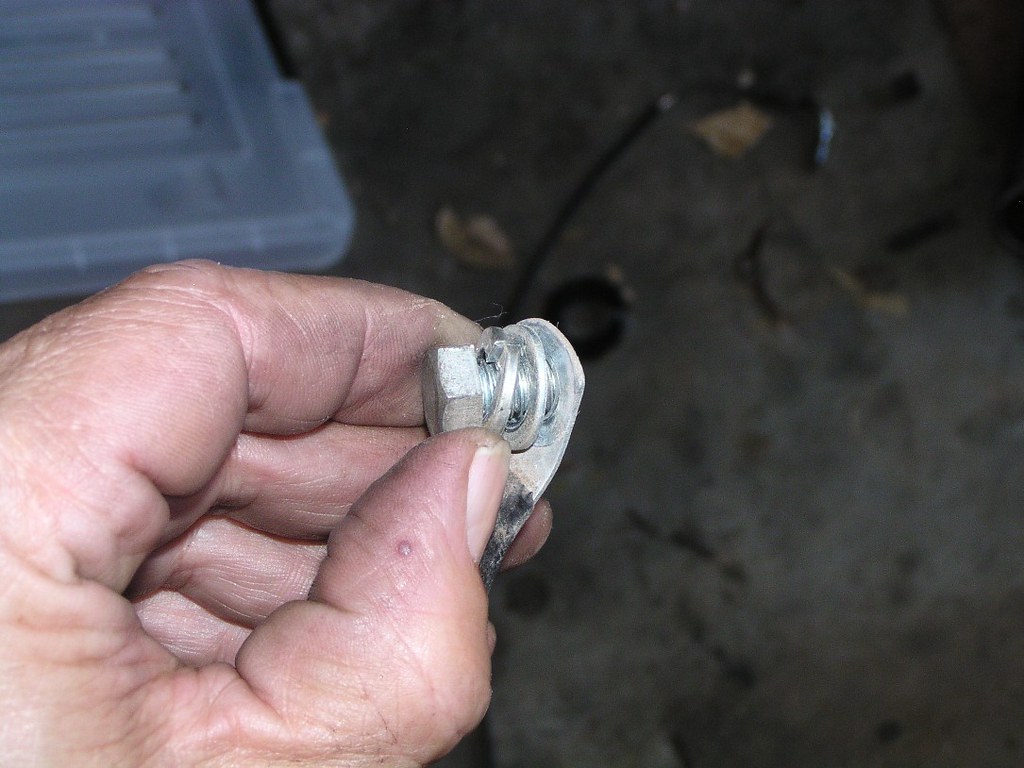
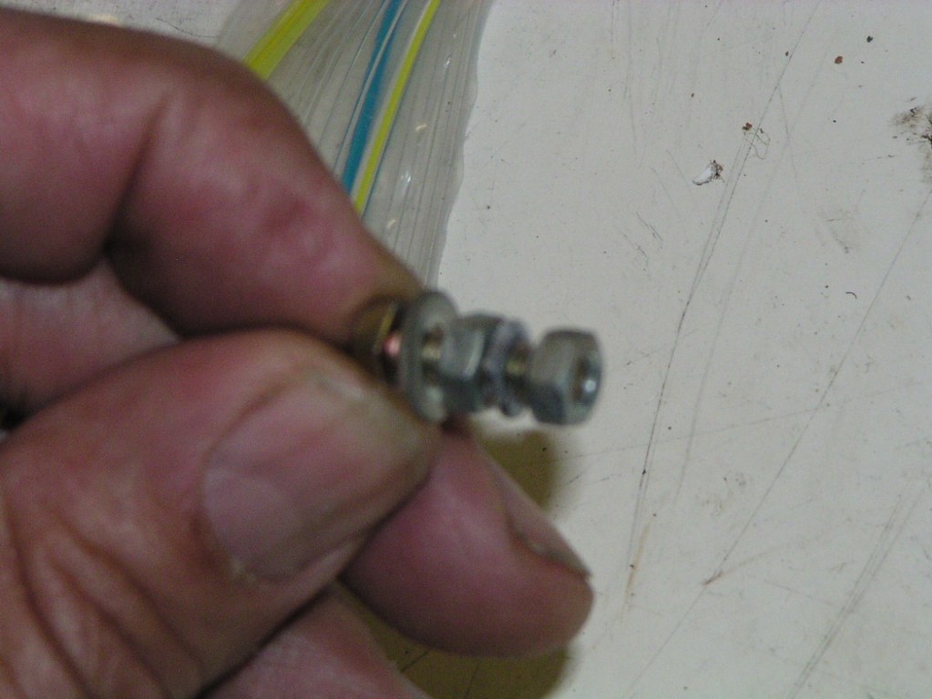
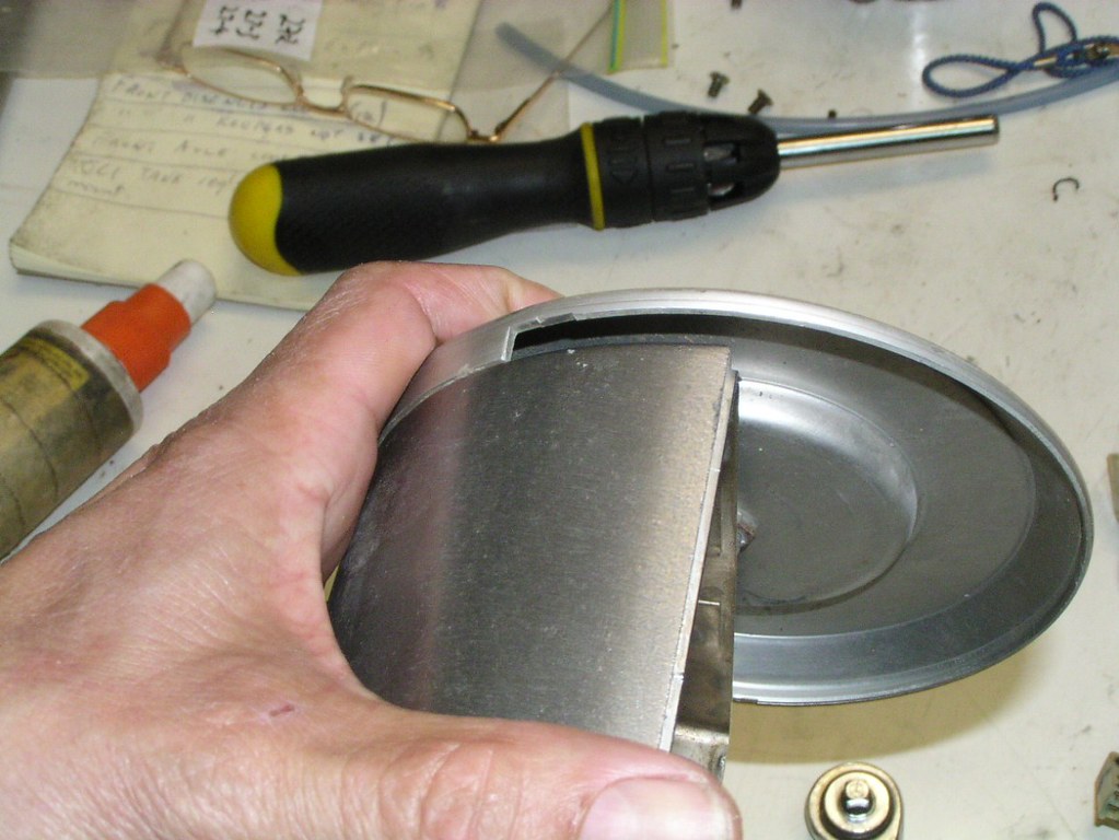
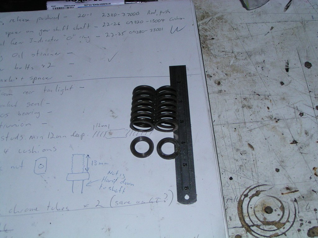
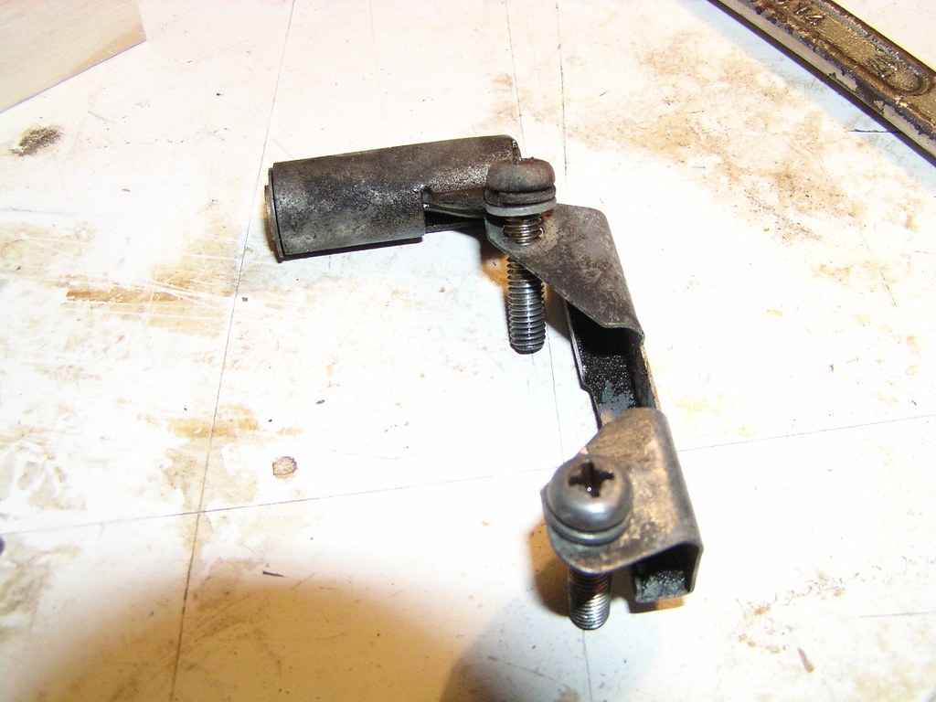
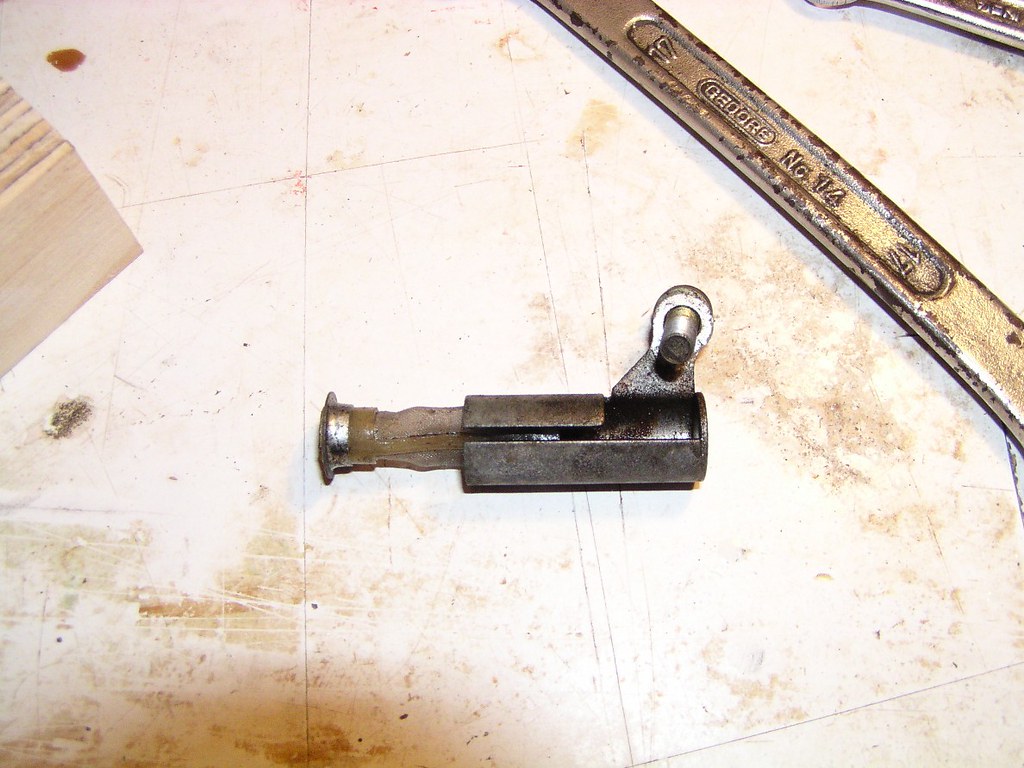
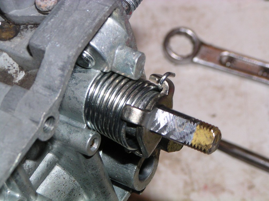
It may be a little difficult to work out what's going on here. This is a spreader tool to help get the cl*tch c*ver off. It's crude, it's agricultural but it works. It's a piece of threaded rod with a regular n*t at one end and a deeper n*t (the brass thing) at the other. The little all*y "thingy" at the other end is nothing more than a spacer to make the tool a tight fit. You just hold the threaded rod with multigrips or similar and undo one of your nuts. It's only millimetres, but it'll be enough to break the hold that the gasket has on the cl*tch cov*r. You can see that it's opened up a tiny gap, that's all that's needed.
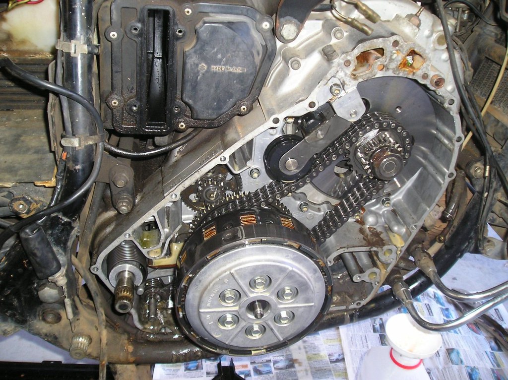
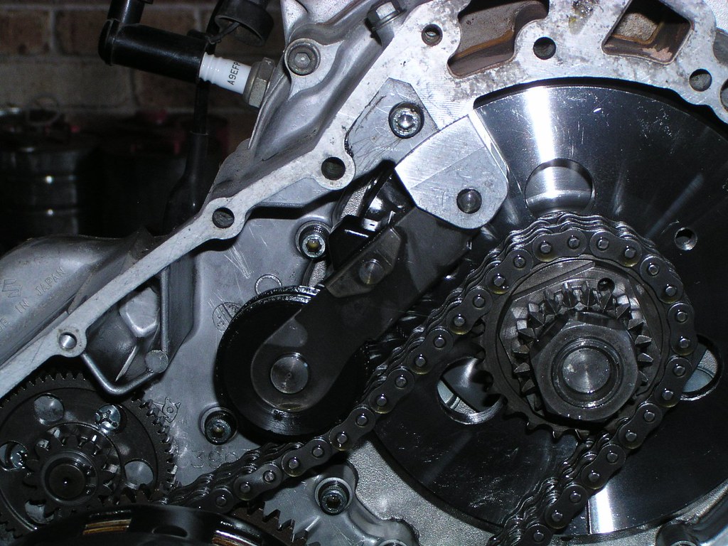
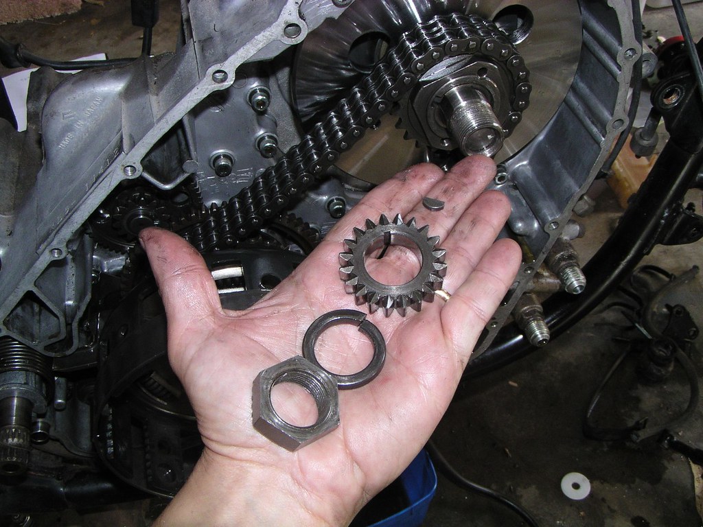
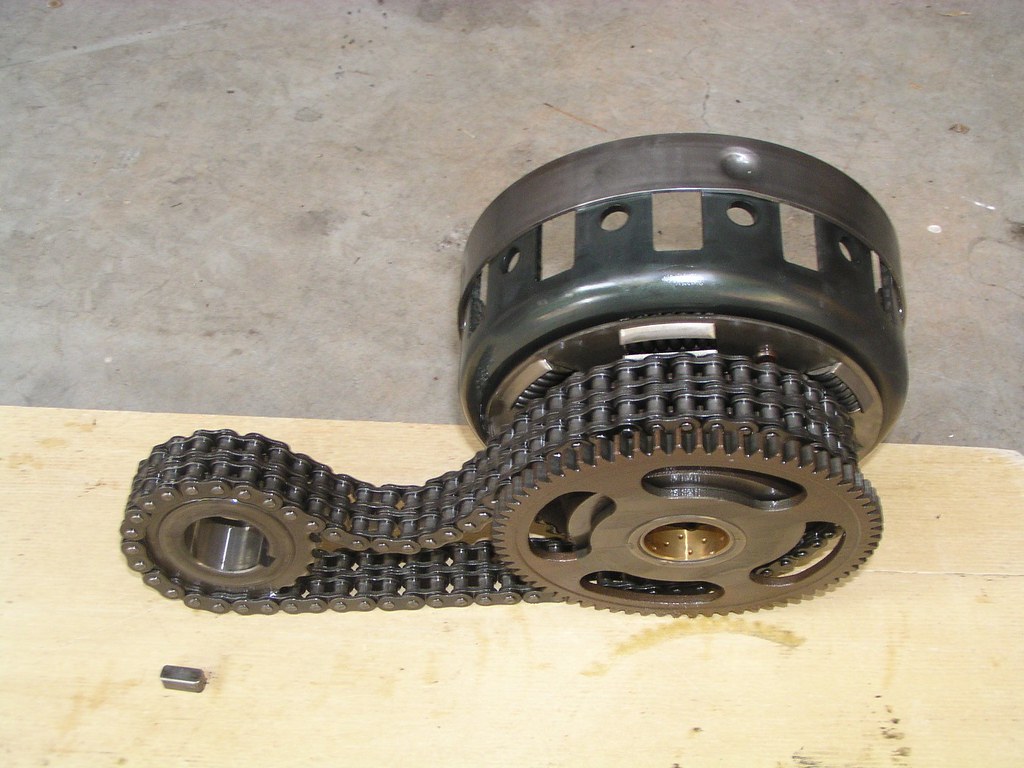
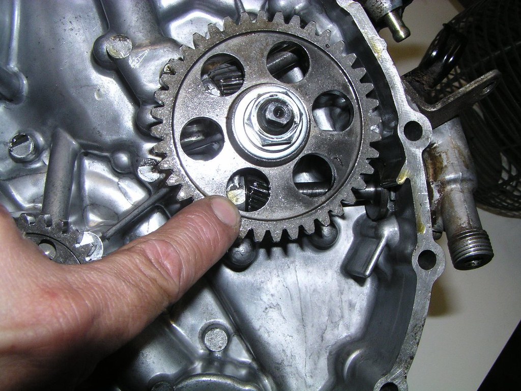
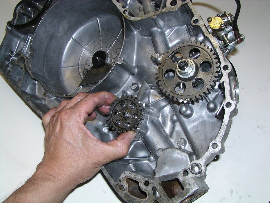
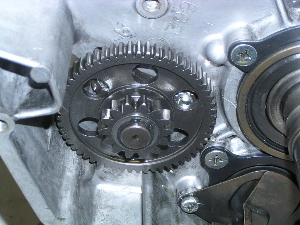
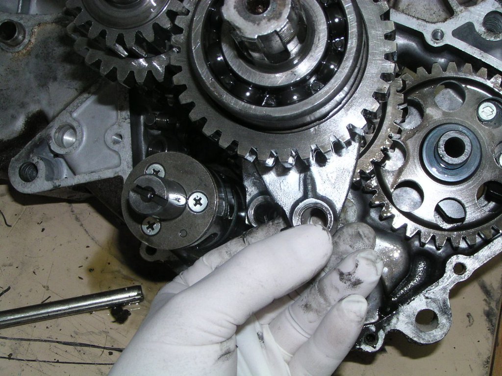
This ge*r on the outside of the prim*ry dr*ve sprock*ts engages with and dr*ves the acc*ssory gearb*x (waterp*mp, o*l p*mp, t*cho dr*ve, tim*ng ge*r). It's essential to correctly align this ge*r on reassembly. You can see the te*th are bevelled on the outer side to allow easy meshing between this ge*r and those held on the inside of the cl*tch cov*r as you push the latter into place. The alignment position is in the manual and is pretty straight forward. However, it's not unheard of to get it wrong and you'll be chasing tim*ng issues trying to figure it out.
Make a mental note of the m*sh between the ge*r select*r te*th
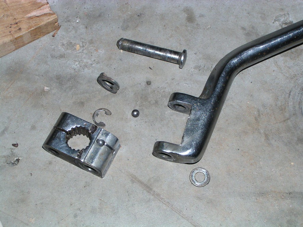
Removing the kickst*rter spr*ng and sp*cers
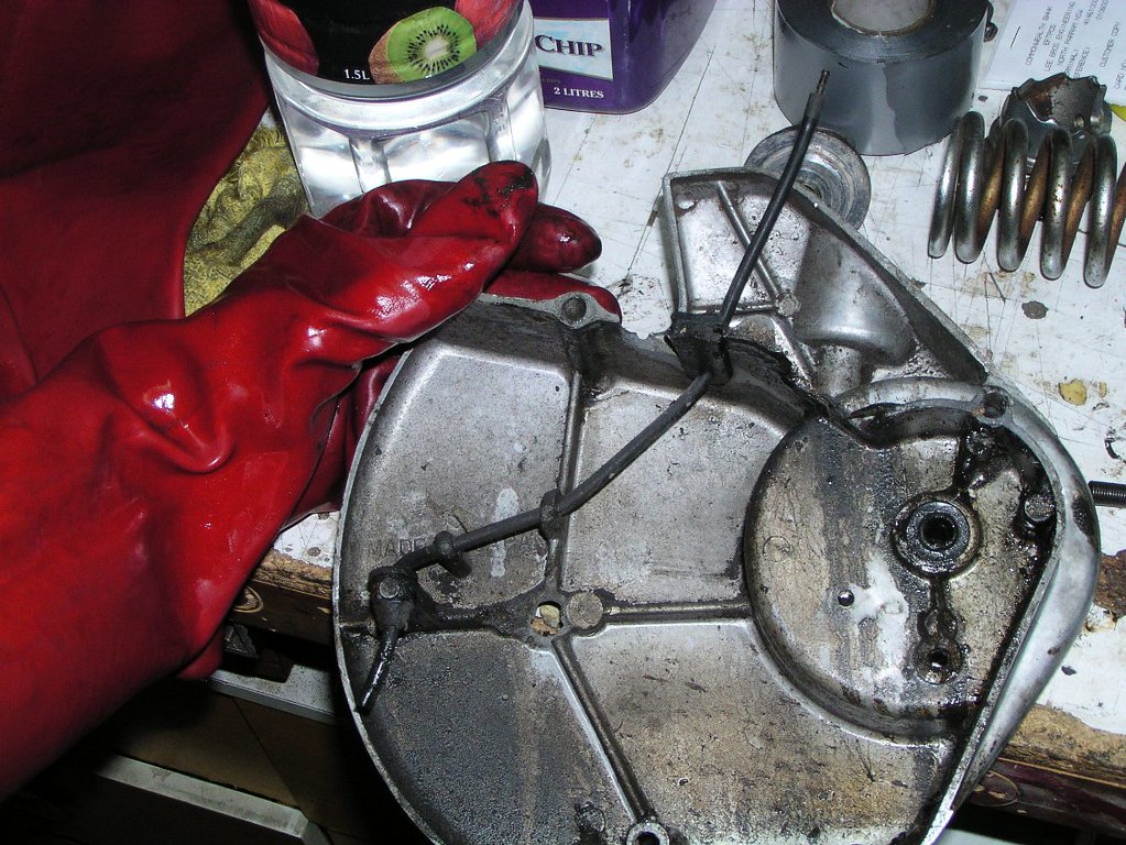
Spr*cket cov*r
Note the cha*n oil*r p*pe and that there is a fact*ry join not far up the tube
Clut*h rele*se mech*nism
Dig*tal Ge*r indicat*r, note the two small spr*ngs. There's not much to do with this but to give it a thorough clean
The next couple of pictures trace the dig*tal ge*r indicat*r wir*ng and cl*mps from its position behind the spr*cket cov*r
What I'm pointing to there is the location of another small flexible met*l cl*mp, clearer in the next picture
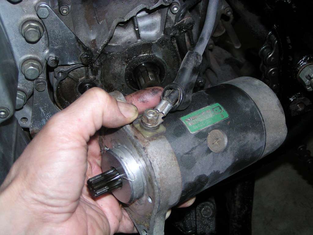
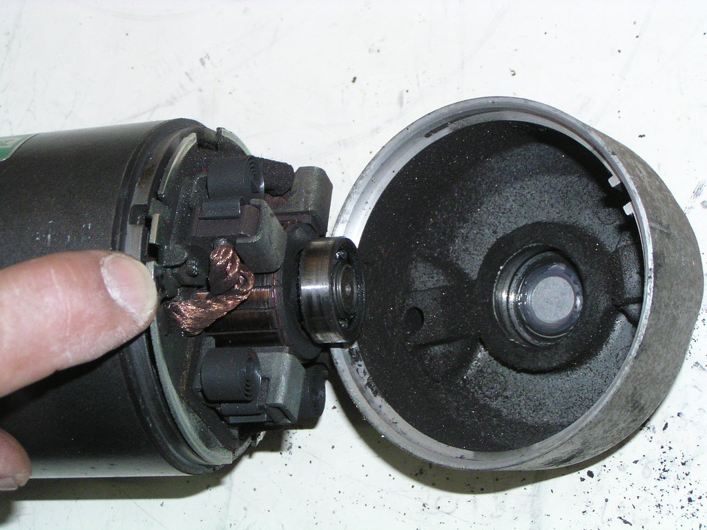
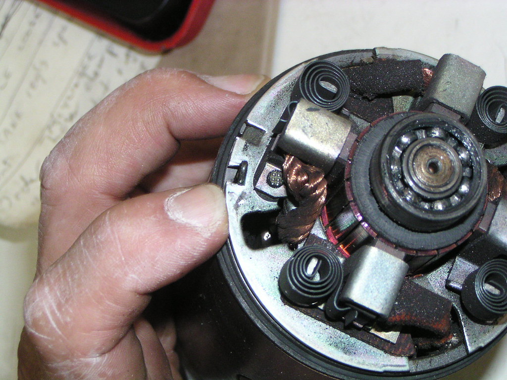
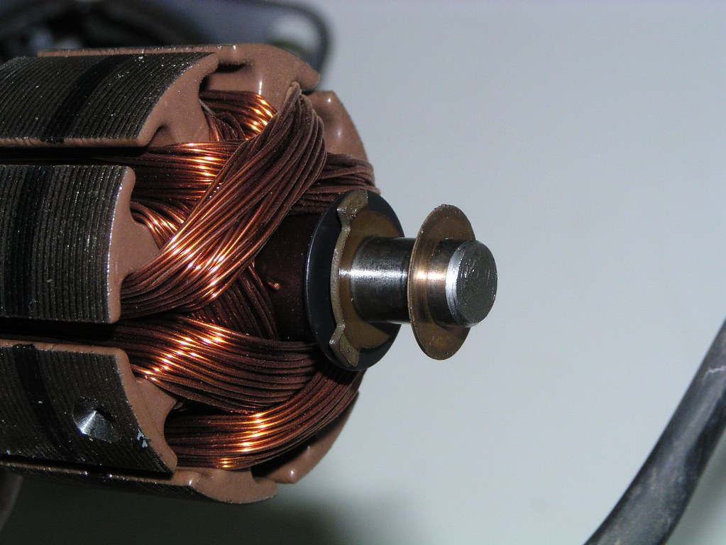
Start*r Mot*r
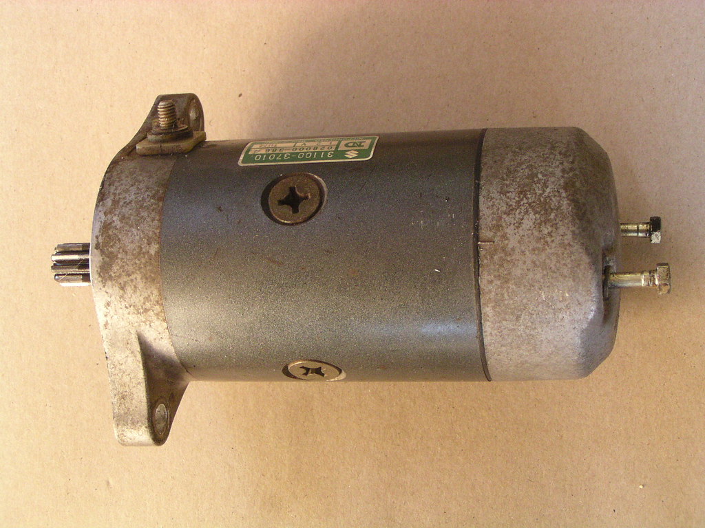
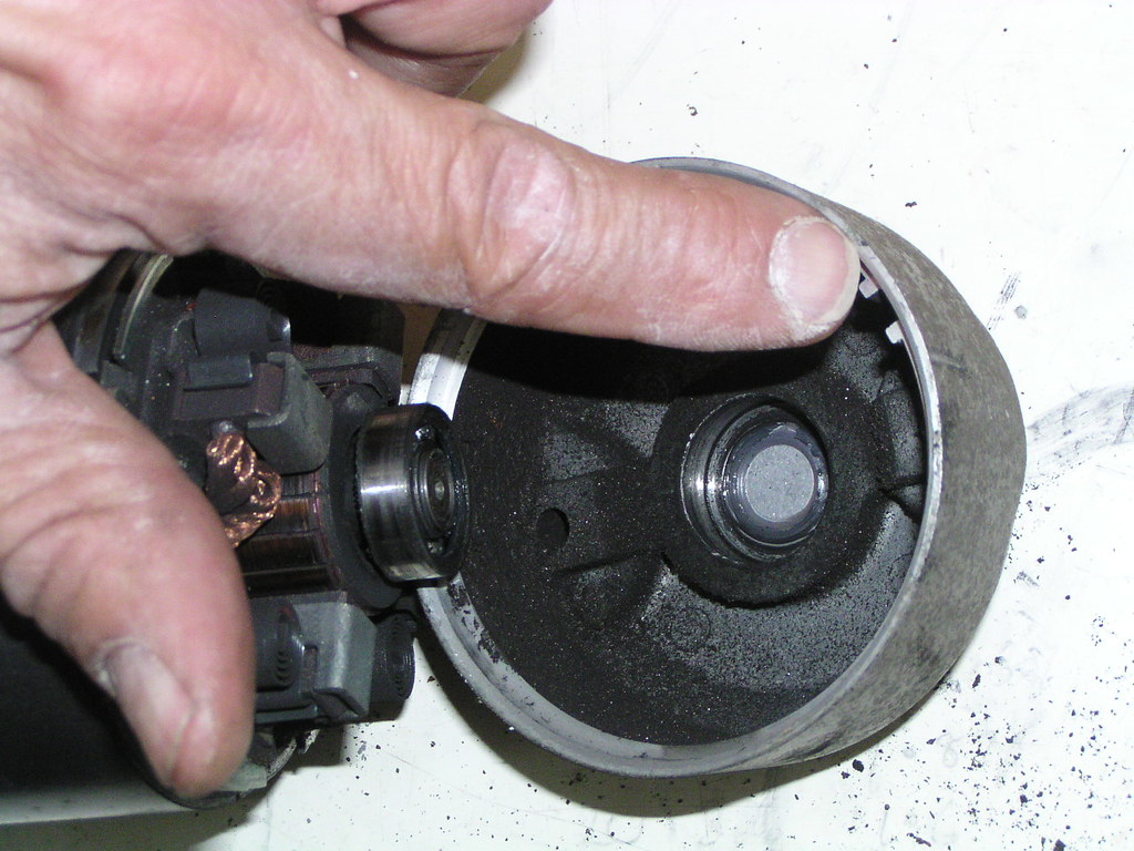
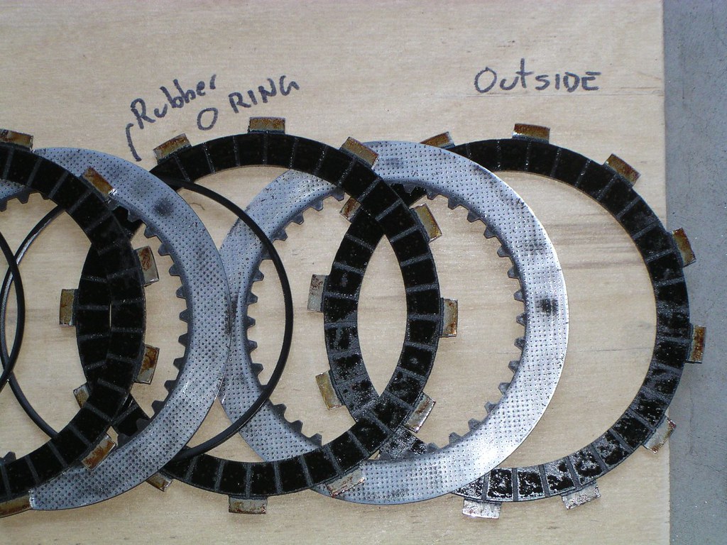
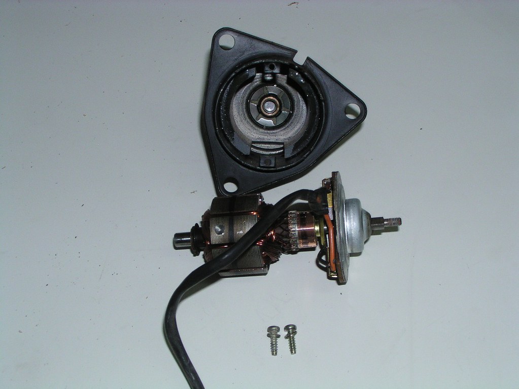
I'm actually pointing to the cutouts but note the square section rubb*r "O" r*ng under my finger that's 'round the circumference of the mot*r
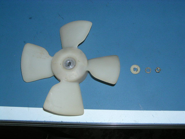
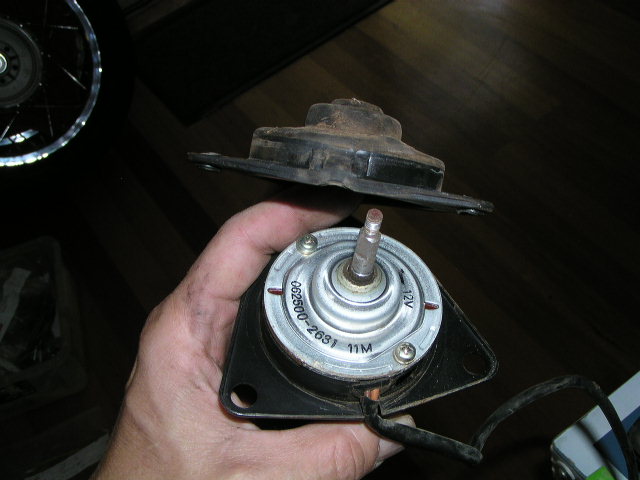
F*n motor and bl*de
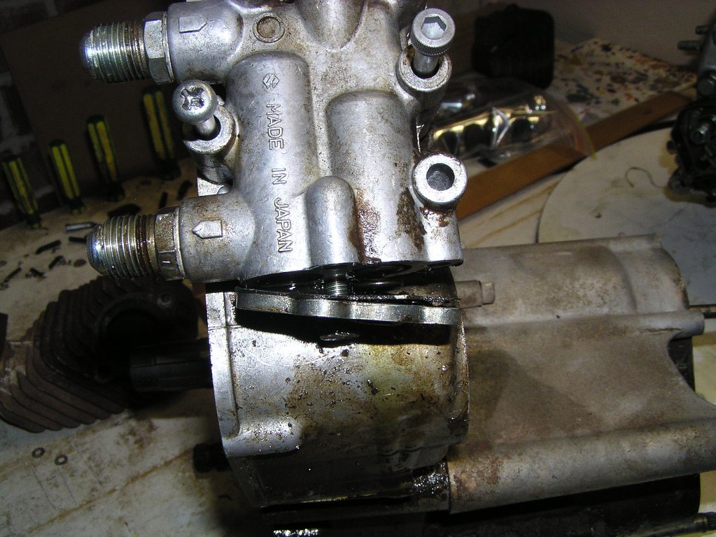
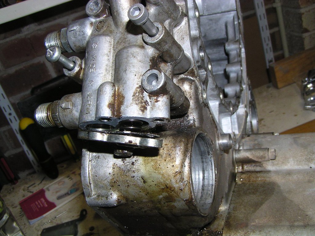
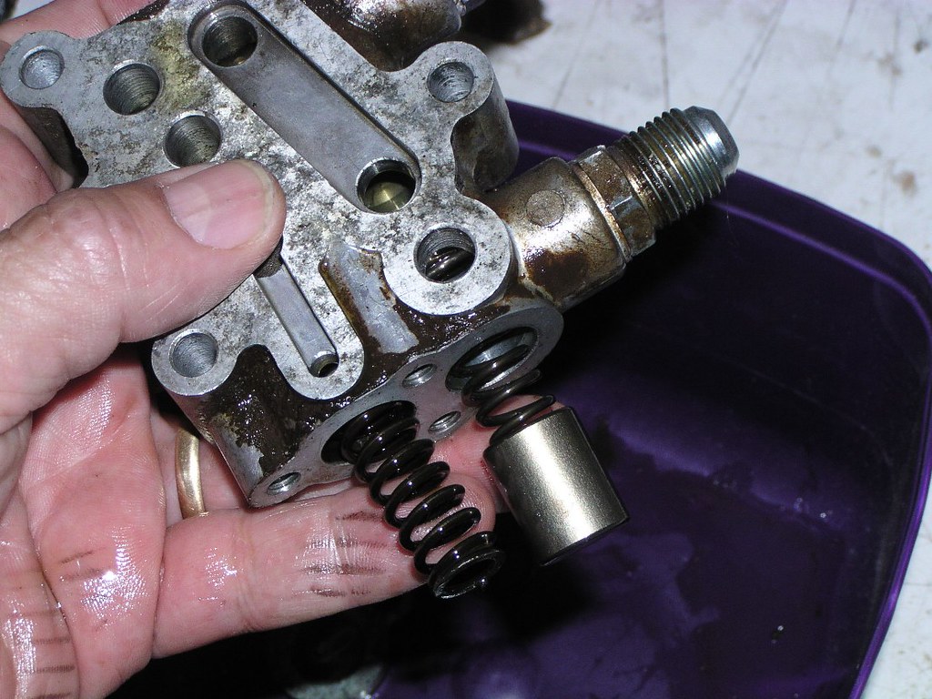
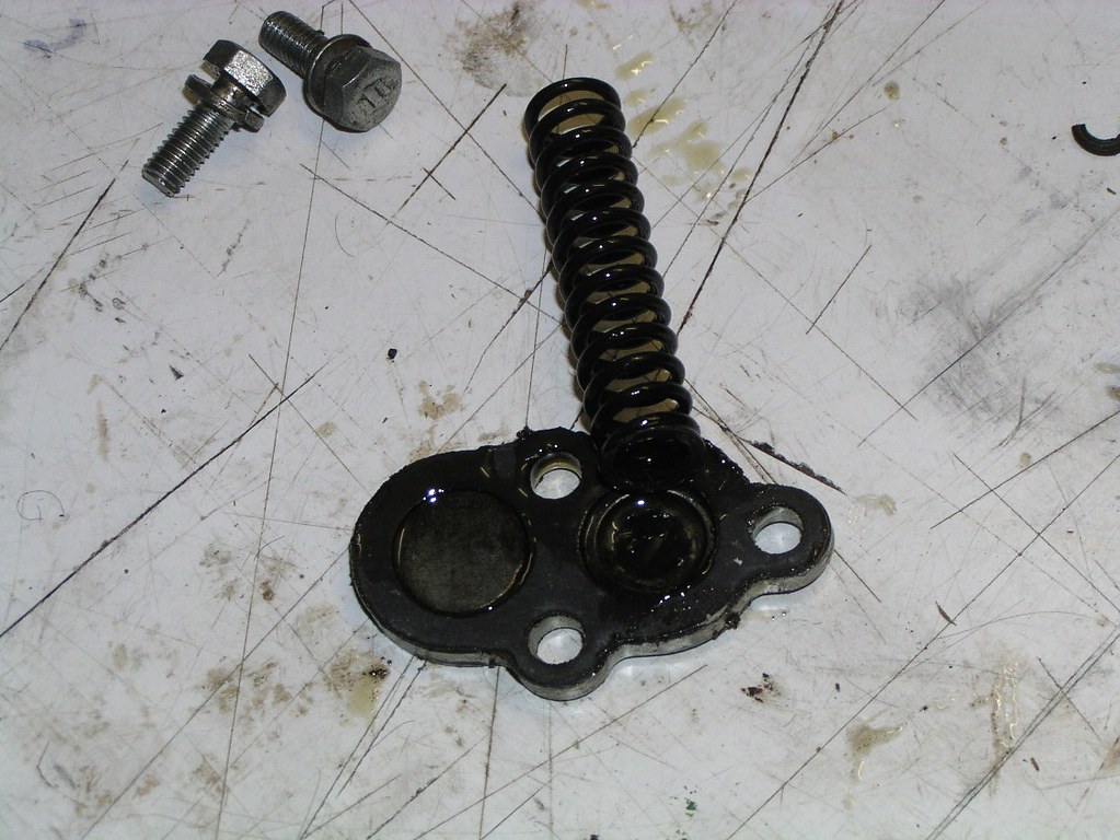
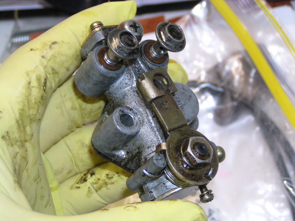
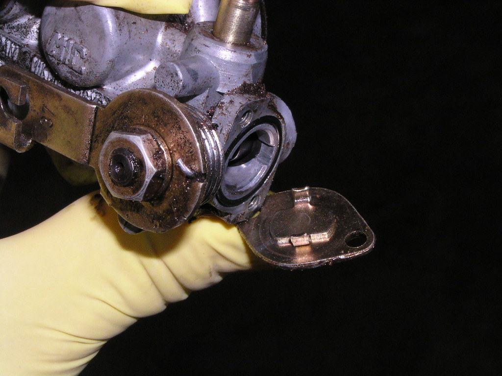
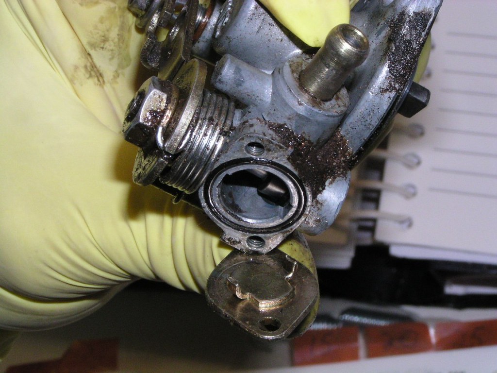
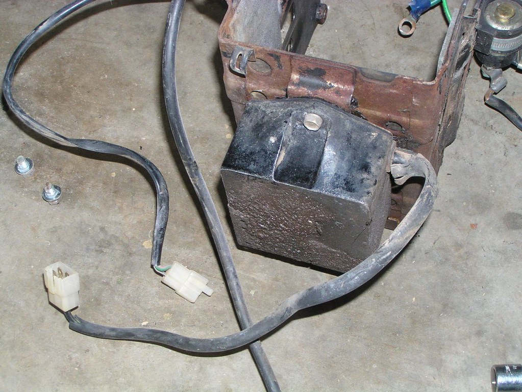
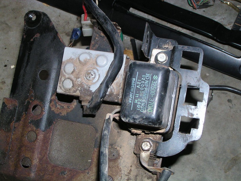
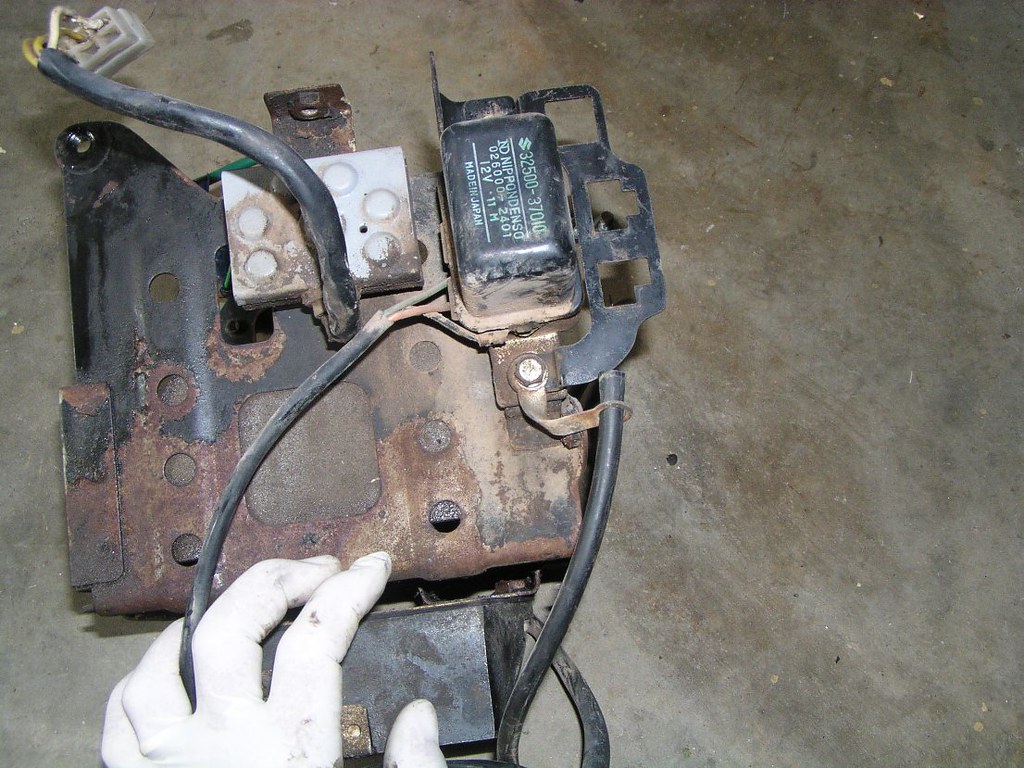
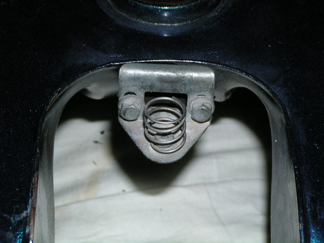
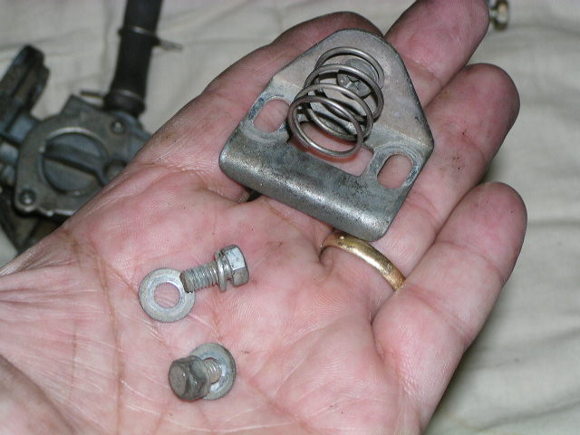
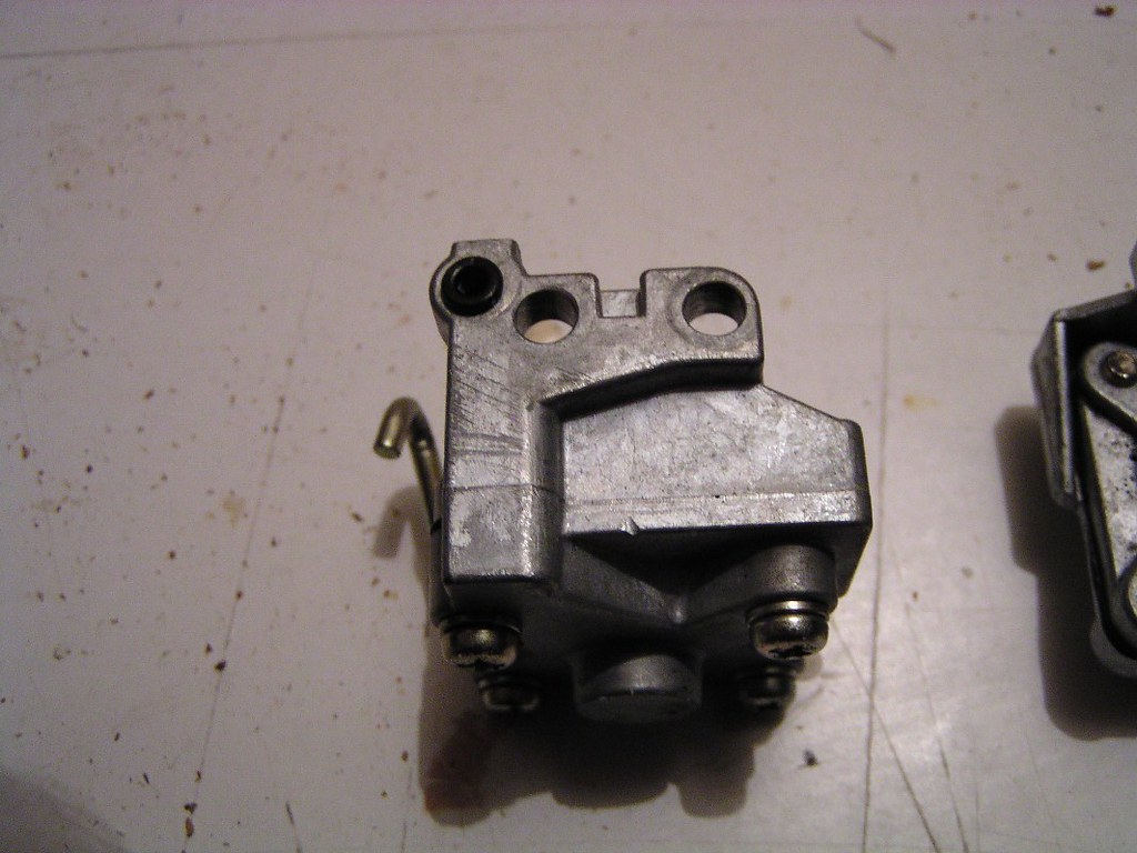
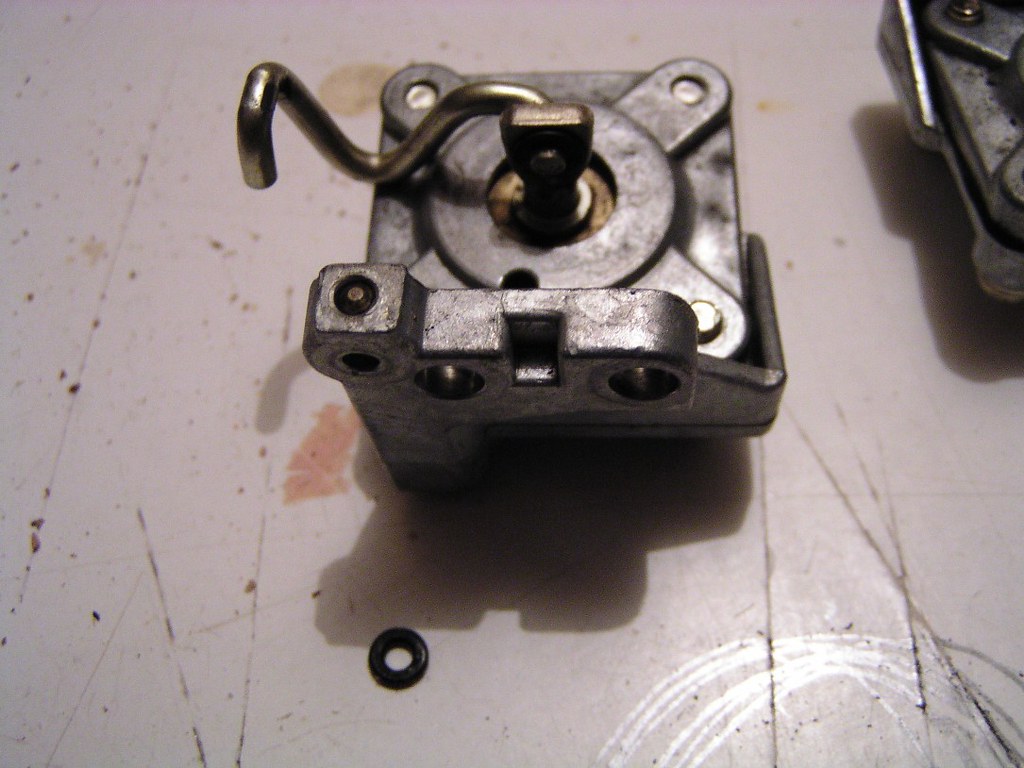
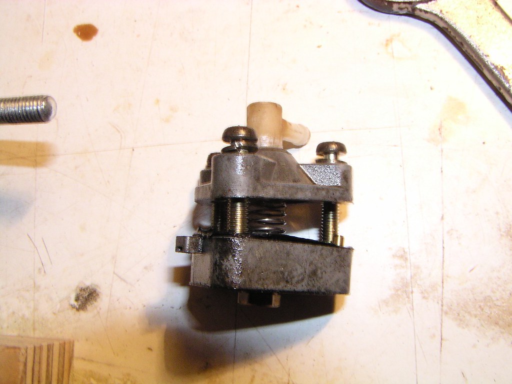
O*l Press*re Regul*tor
The first photos show the regul*tor still attached to the c*se so the orientation is obvious. Some of the following pics orientation is not so obvious. One pist*n is at the top of the spr*ng, the other is down the bottom. Keep the p*rts bo*k handy on reassembly and don't mix these sides up.

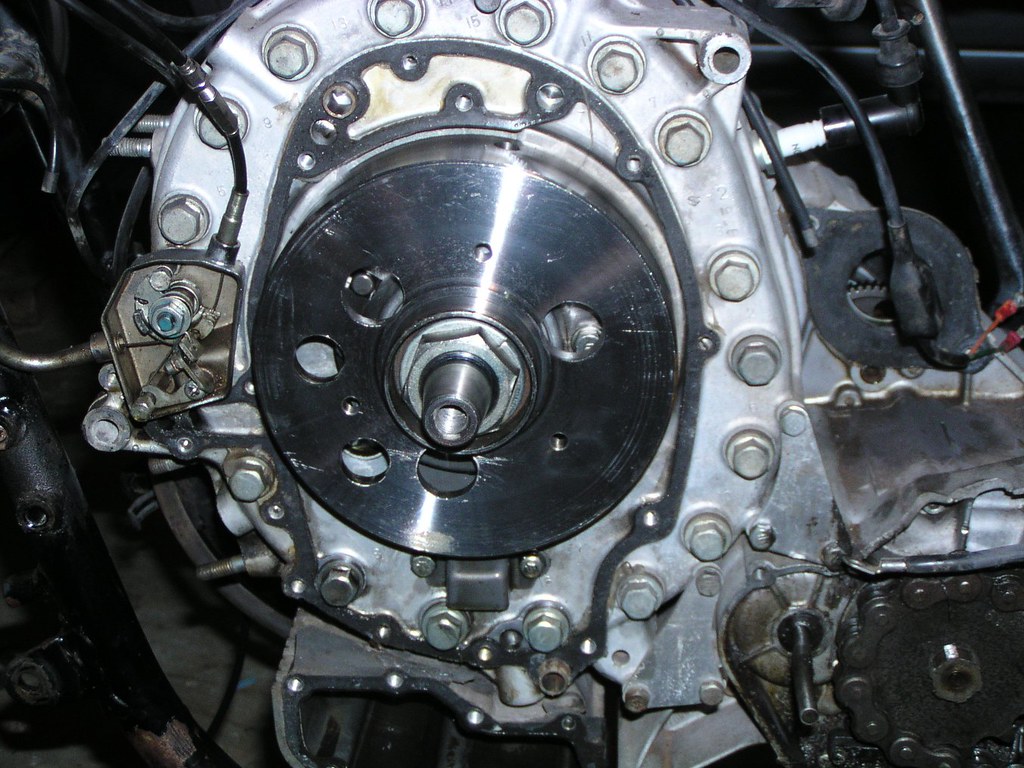
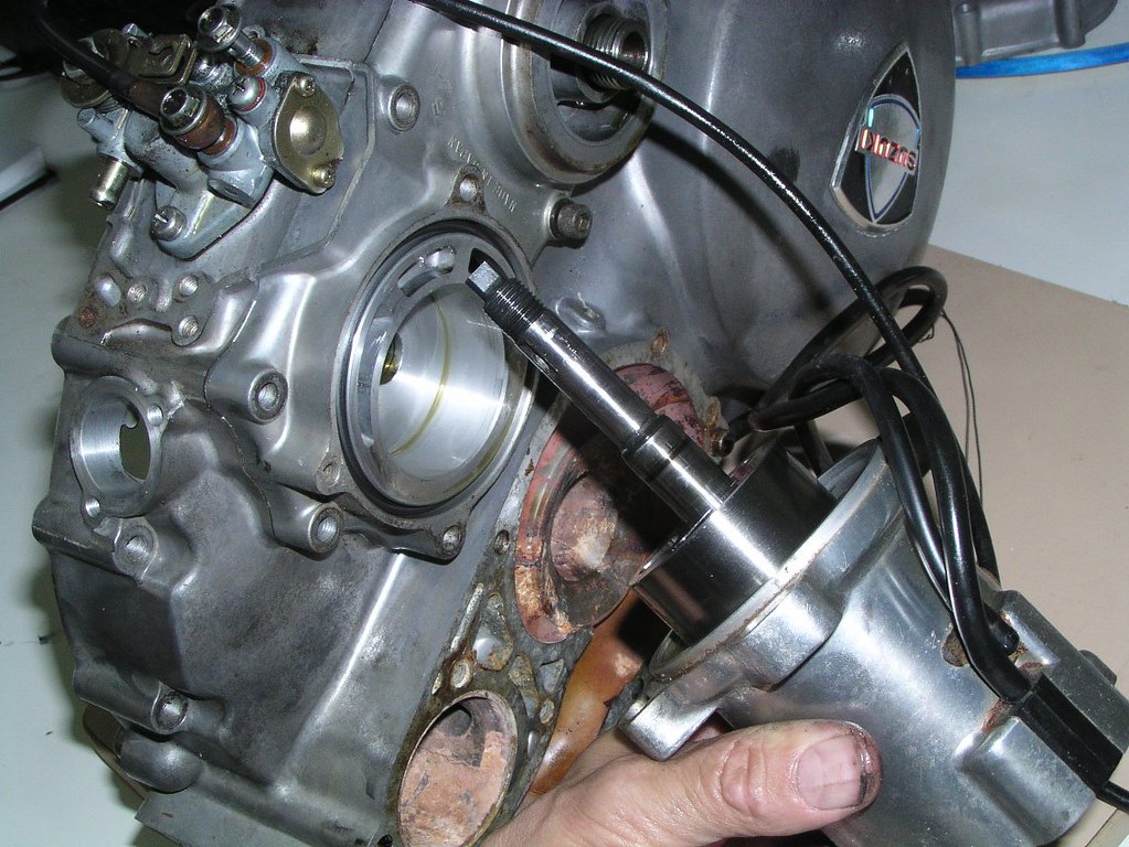
Prop*r Un*t- removing it from the fr*me is pretty obvious, the following are just for interest
Right side
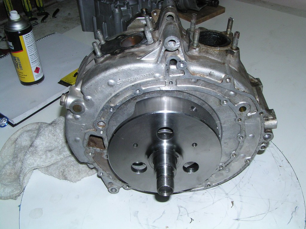
Left side
Ap*x se*l visible through the exha*st p*rt. Note the carb*n buildup. This is a relatively low mile eng*ne, probably 10 to 20,000 miles
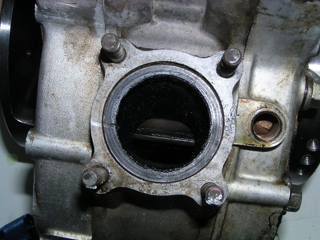
P*rt V*lve closed
P*rt V*lve fully open. The two holes in the gask*t and cas*ng below the PV are the prim*ry p*rt inducti*n tr*cts. The sec*ndary p*rt ind*cts through the PV apert*re
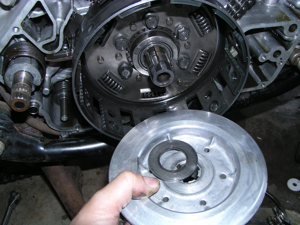
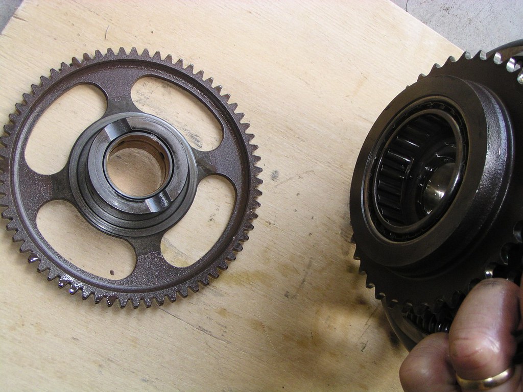
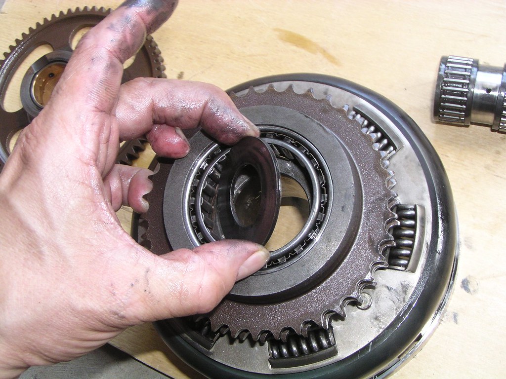
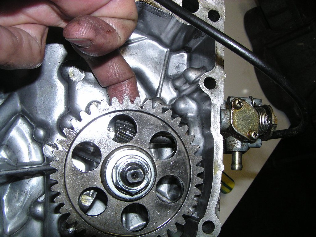
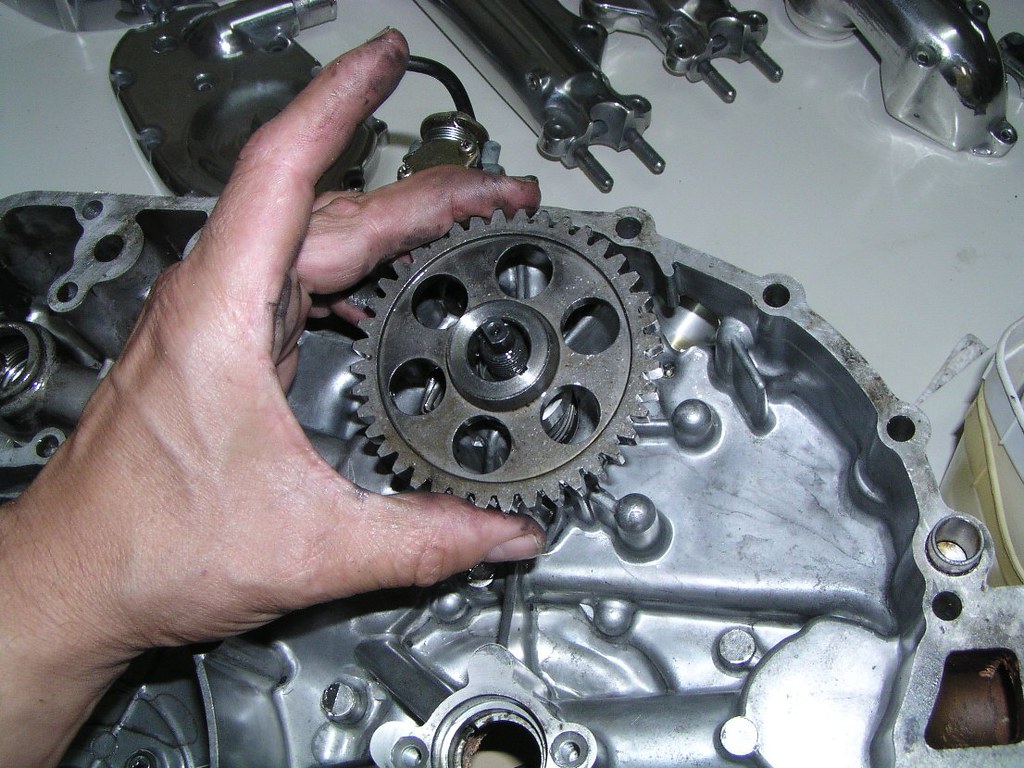
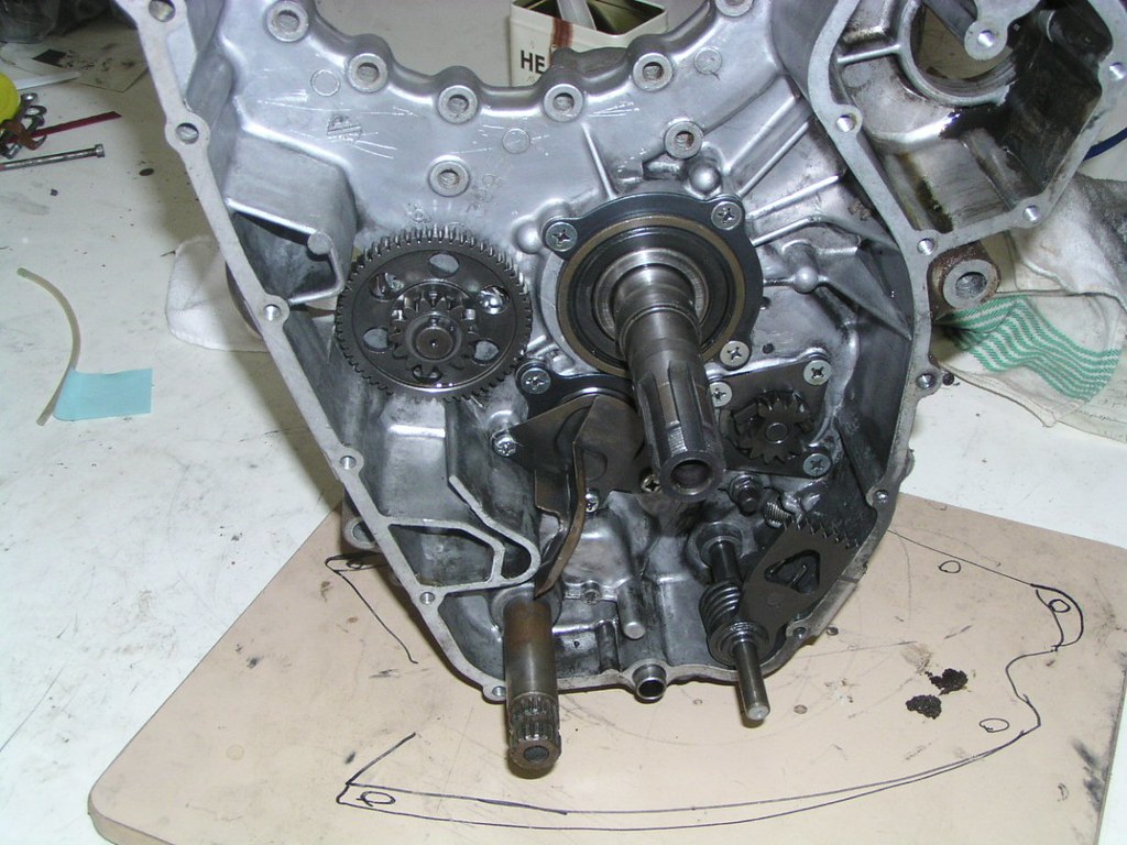
Before we start pulling off access*ries, here's just and overview of the two main ge*rs inside the cl*tch c*ver. These two ge*rs m*h with that ge*r on the end of the cranksh*ft which had bev*lled edges shown earlier. Ignore the fact that my hand is on the waterp*mp dr*ve ge*r. The next series of photos deals with what's under the large ge*r. That ge*r is connected to the p*int c*m sh*ft (inside the p*ints ho*sing). That sh*ft has a helic*l ge*r which dr*ves both the tach* dr*ve and the met*ring o*l p*mp. Before it enters the p*ints h*using, it's also dr*ving the m*in o*l p*mp which sits between the p*ints h*using and the cl*tch cov*r cas*ng

T*cho dr*ve
The t*cho dr*ve ge*r and sh*ft is below the large c*g wheel my finger's on.


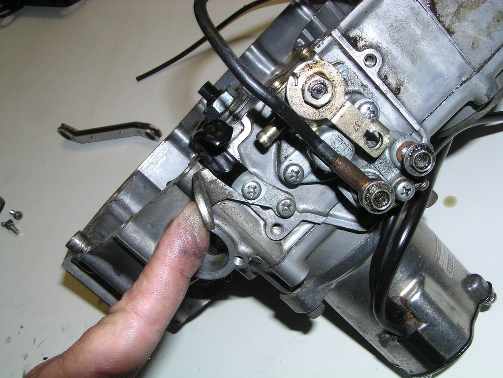
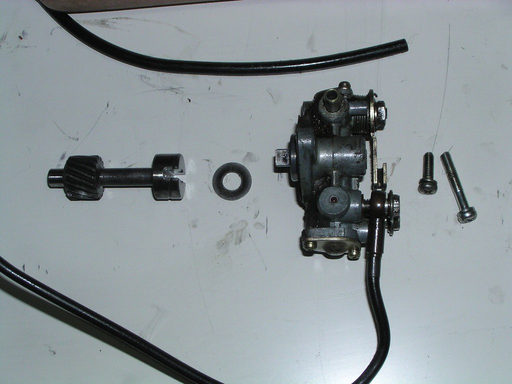
Met*ring O*l P*mp
This picture has the cas*ng almost upside down. You're looking at the brack*t that holds the c*ble linking the met*ring p*mp fl*w contr*l a*m to the thr*ttle and the flex*ble cl*mp for the o*l l*nes
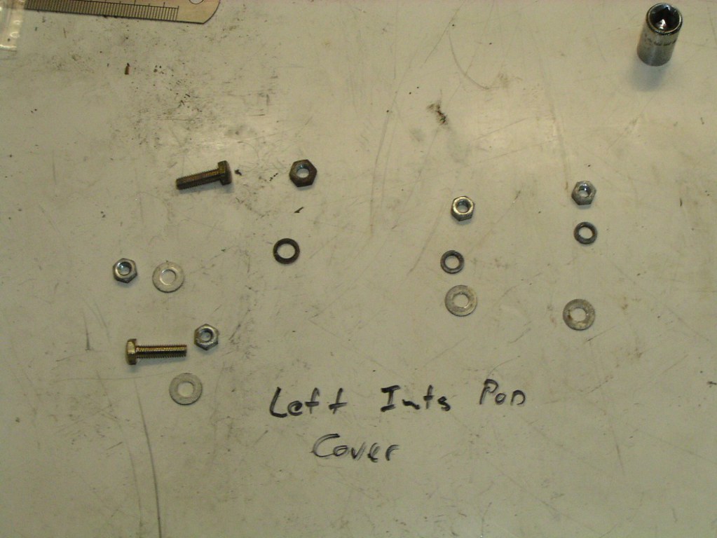
This'll help you remember what these are when you find that in the bottom of the bucket load of stuff you sent to the z*nc plat*ng shop
Stating the obvious once again, the p*mp dr*ve and sh*ft is below the large c*g
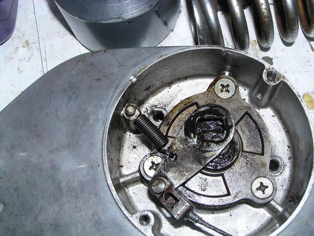
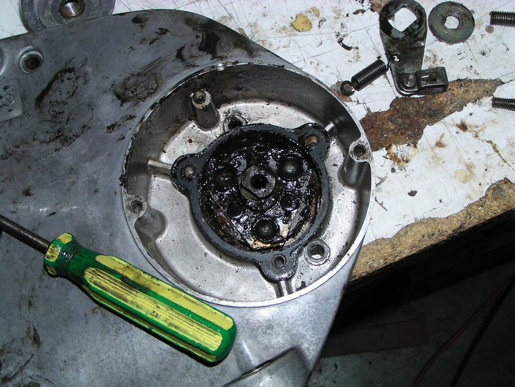
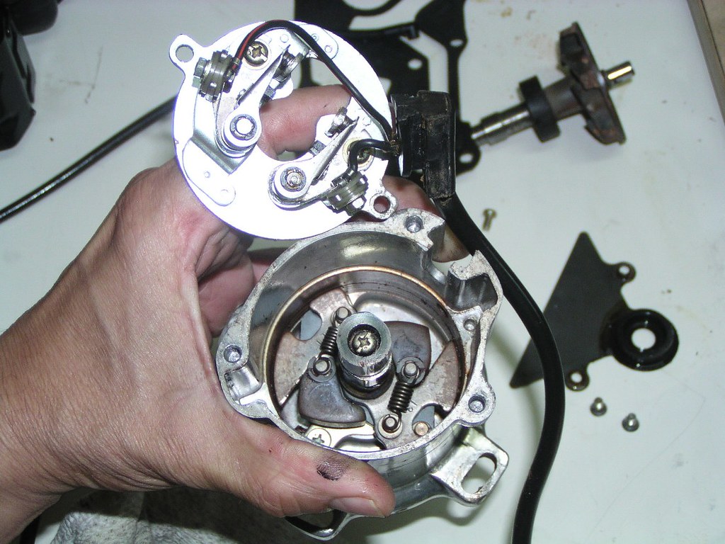
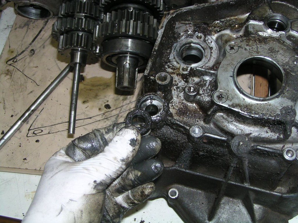
Disassembly of the p*ints ho*sing ass*mbly which includes the m*in o*l p*mp
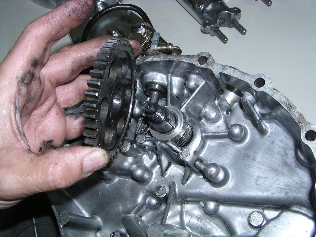
While I'm holding the p*ints c*sing in my hand, you're actually looking at the m*in o*l p*mp h*using and pass*ges still attached to the large cl*tch c*ver
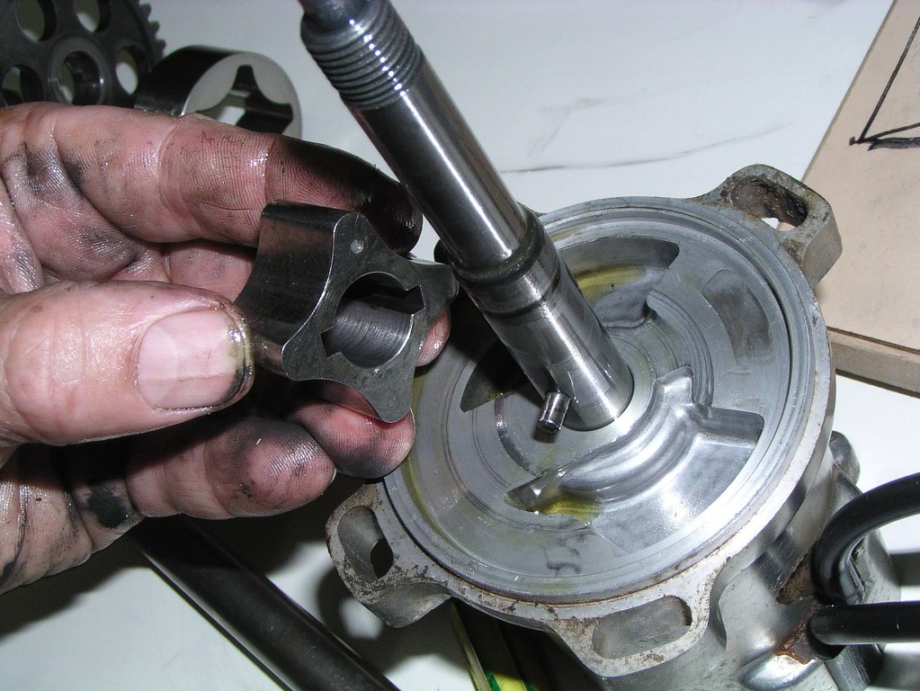
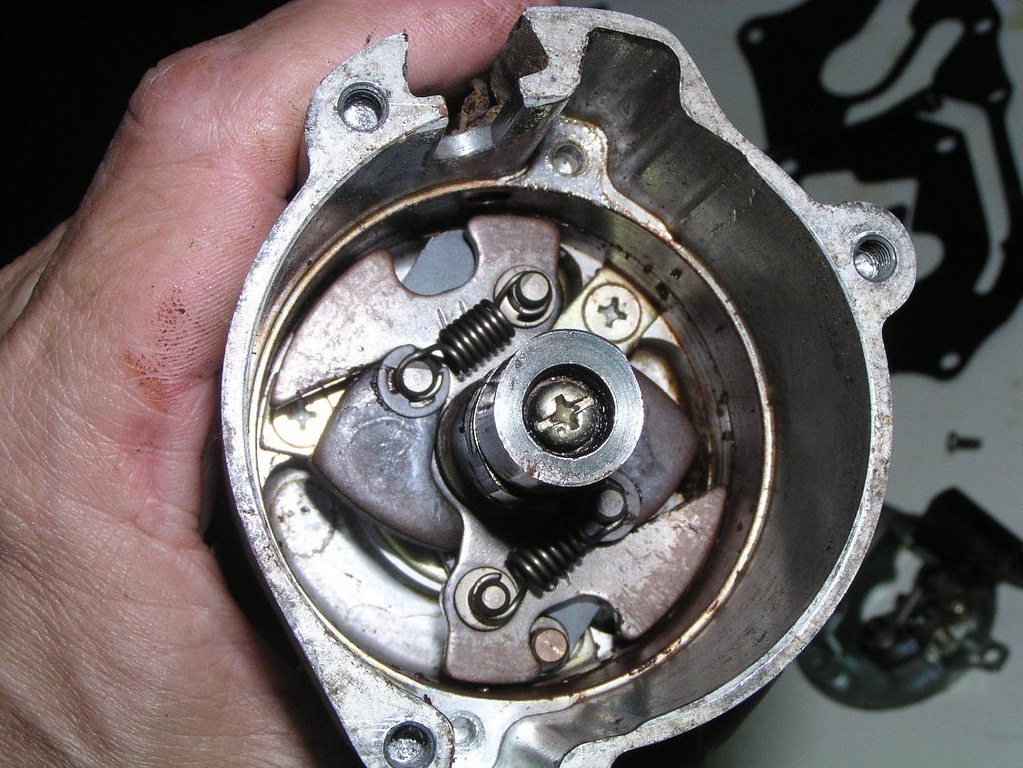
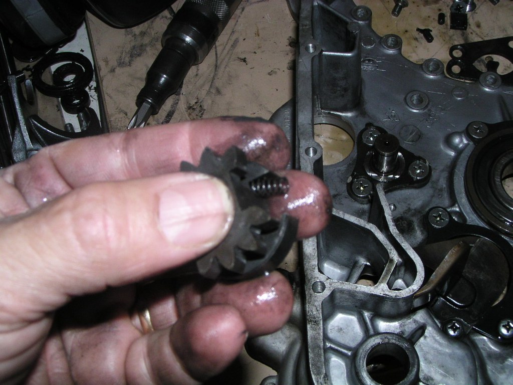
Looking down on the troch*id o*l p*mp l*be
Notice the dot on the part just under my thumb
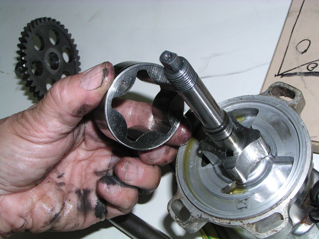
Note that this is being disassembled "upside down". When you're reassembling these into the p*mp c*se on the cl*tch c*ver, those d*ts will be fac*ng "up" or out, ie at you as you put it together

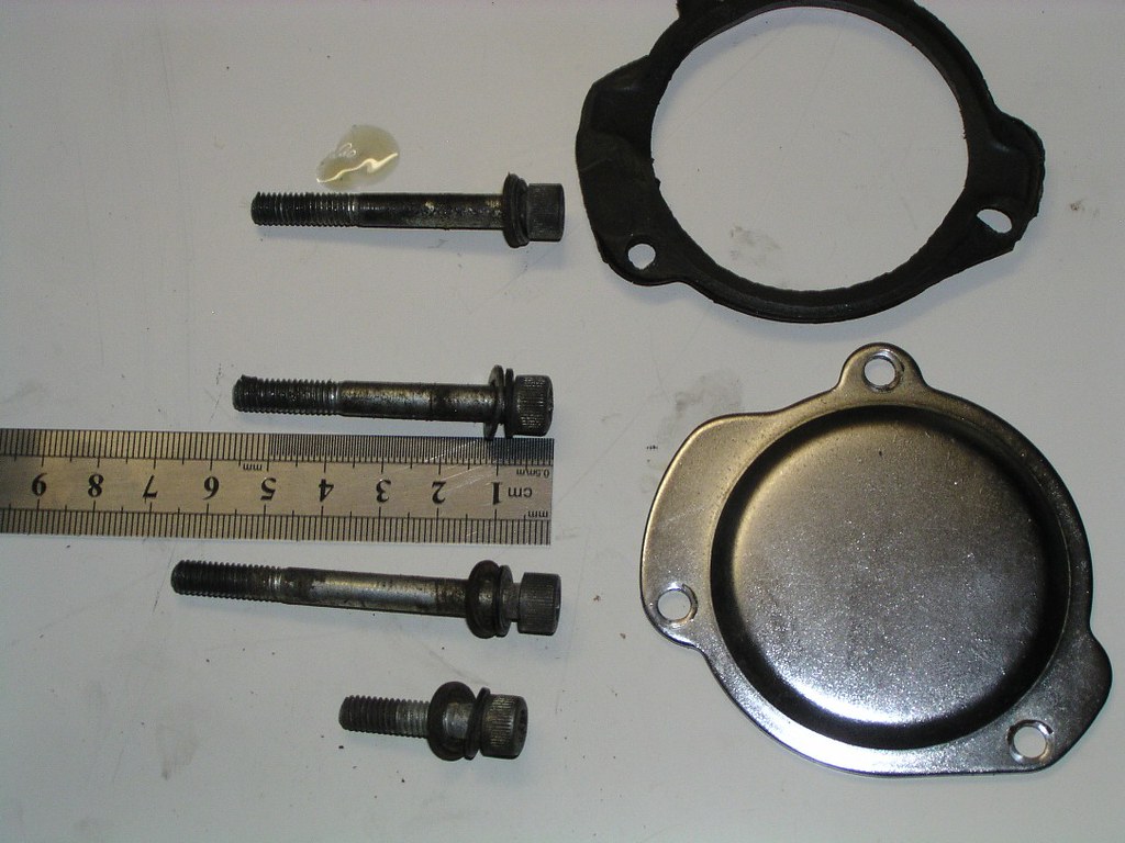
If you're a bit anal with the accuracy of your restoration, note that these are not ordinary Phill*ps scr*ws
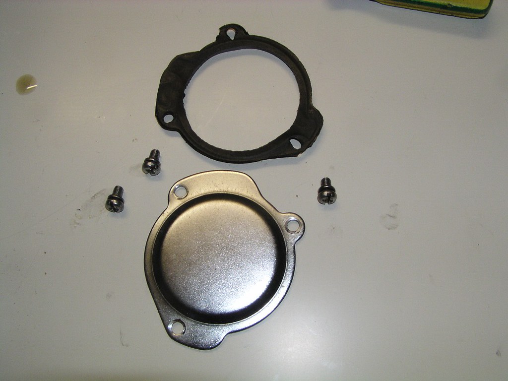
Typical Suz*ki, hard pressed to get more than 2 b*lts the same size. P*ints c*se b*lts
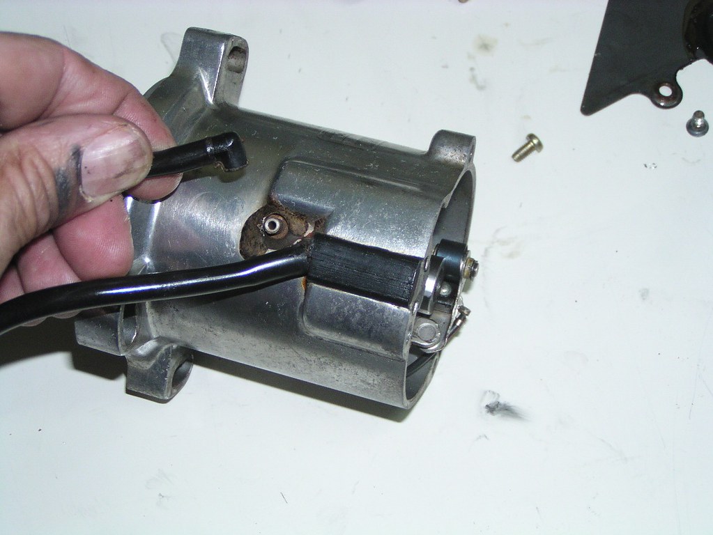
P*ints h*using v*nt p*pe (discussed earlier)
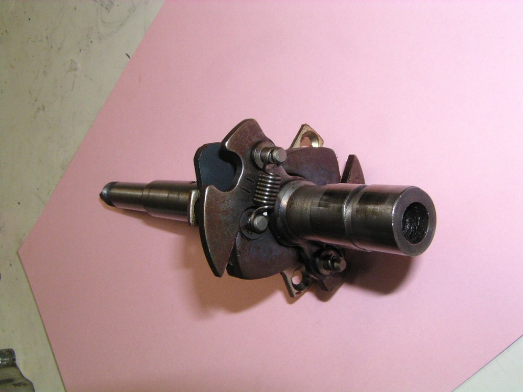
You'll notice the number "1_1" and "1_3" stamped on these count*rweight pl*tes. There's an amendment to the fact*ry serv*ce manu*l. Where it says d. Reassembly, p*int (a) "When installing the cont*ct break*r c*m, be sure to bring the roll*r on the adv*ncer we*ght pl*te into the notch marked "1_1" (the value of the adv*nce angl*)" The "1_1" has to be changed to 1_3.
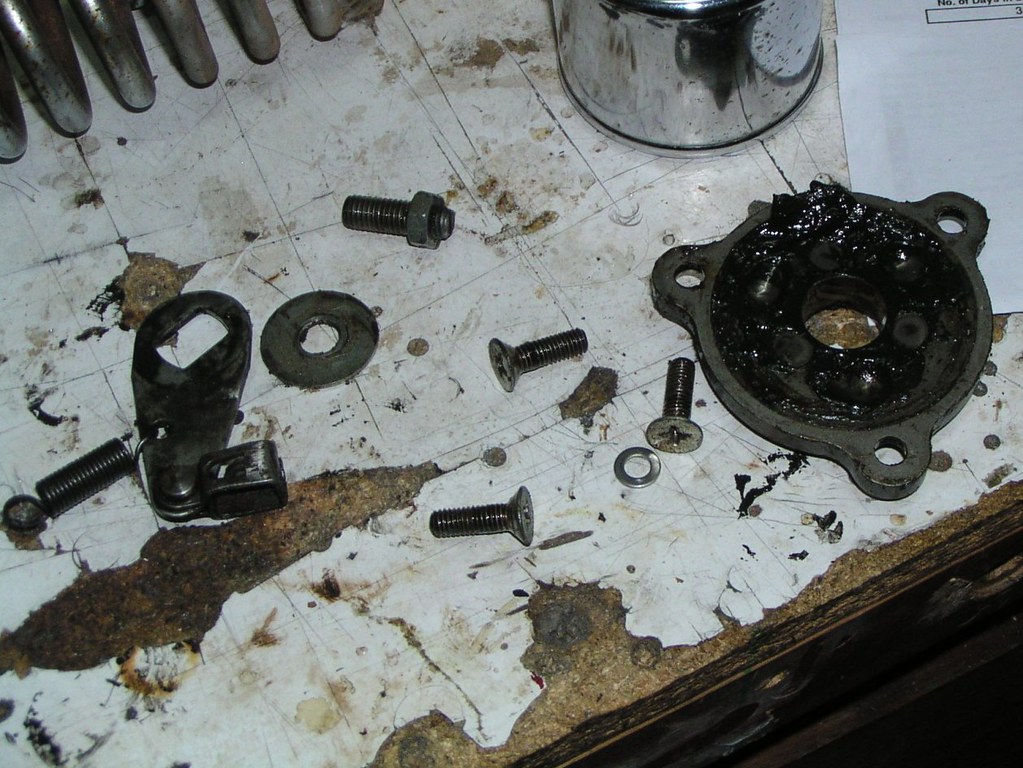
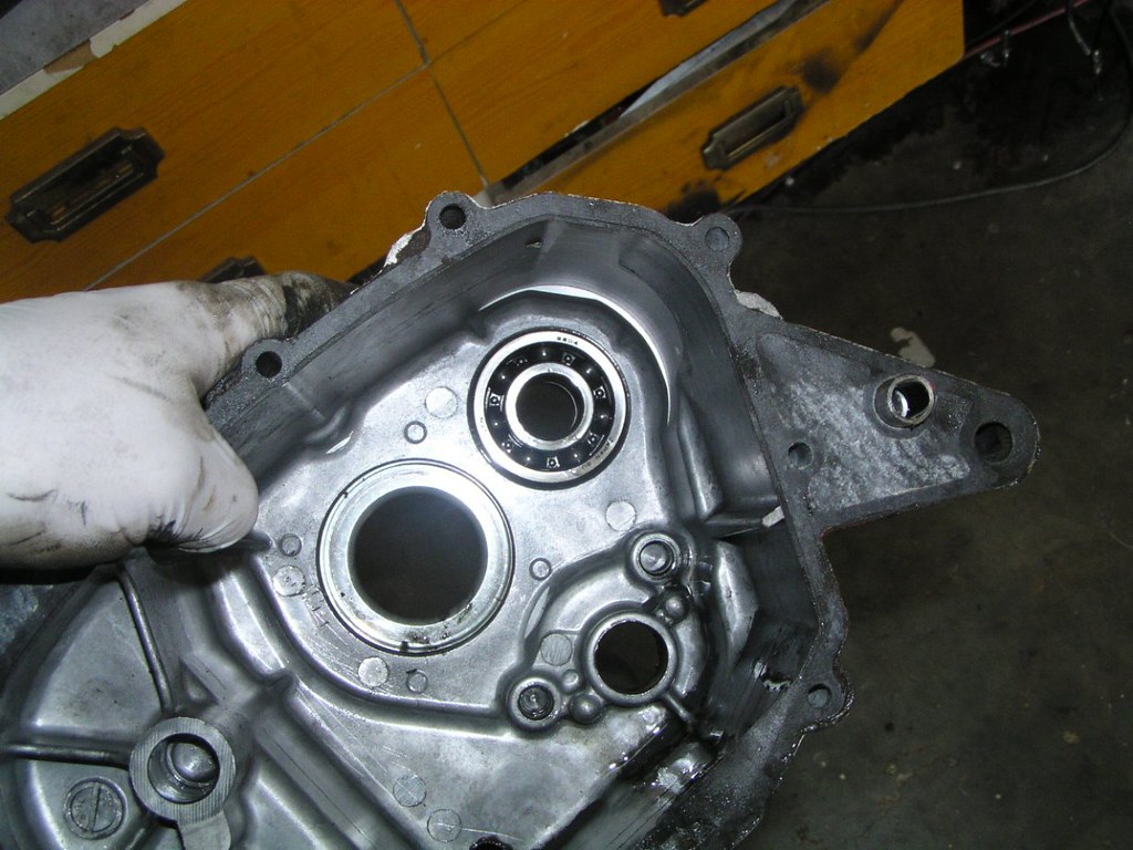
Looking at the base of the p*ints h*using
This O_ r*ng caused me an enormous headache on the rebuild of this bike. I used a non genuine part and it turned out to be a tiny bit thicker than the original. It resulted in the whole o*l pump c*sing not seal*ng enough to allow the p*mp to work properly and subsequent l*w o*l press*re. I was lucky to find it as it was enough press*re to extinguish the o*l l*ght but way too low for the b*ke. It was a nightmare trying to find the problem. I only buy the genuine Suz*ki item which is ridiculously priced

If you buy this se*l from an over the c*unter be*ring shop, you may find that it's thicker than the original. They apparently no longer supply se*ls like this in the original thickness made for this eng*ne. You can make it work, but you have to mach*ne the spac*r in the previous picture down a bit to make it all work. After this b*ke, I just cough up and buy the expensive original (it has a met*l out*r c*se unlike the all rubb*r modern alternatives)
One other thing, don't put this se*l in backwards. It has been done. You'll p*mp a heap of your s*mp o*l into the cl*tch/transm*ssion in minutes

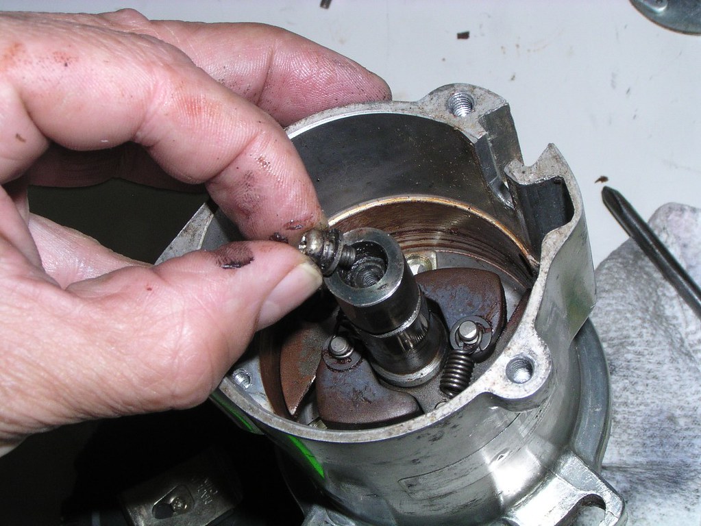
Finally we get to that hel*cal ge*r that was actually driv*ng the t*cho and the meter*ng p*mp

For the restoration nerd. I've been unsure of how to finish a couple of cas*ngs on the RE5. This troch*id o*l p*mp cas*ng (under the p*ints h*using), which I'm sure has never been off the bike or rest*red in any way, shows what looks like peeling pa*nt. On other b*kes that I can be sure are also original, I've found no coat*ng, just a fl*t all*y finish. As with many things on this b*ke and others, I don't believe you can definitively make a call on some items. Depends on what was supplied to the fact*ry on the day (methinks)
The Meter*ng O*l P*mp
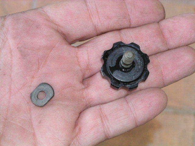
Note this little wash*r, it's a loose fit so it's not instantly obvious that it goes here on reassembly
The Phill*ps he*d scr*w a the top of the photo is the o*l l*ne a*r ble*d scr*w - remember this when you're getting ready to re-commission the b*ke and refilling o*ls
I didn't disassemble the p*mp any further than this. Replaced the O_ r*ng for the "why not" excuse but no need to tempt fate. I believe these p*mps were designed to run around 90,000 mil*s before failure. Real world use, they'll go even longer
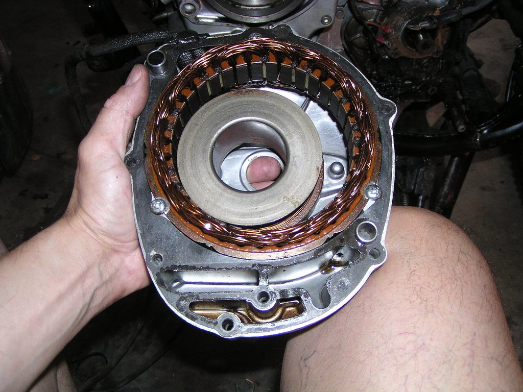
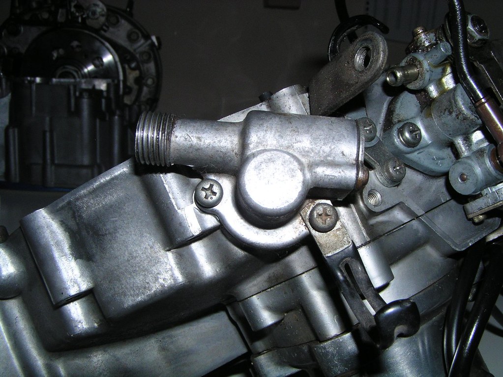
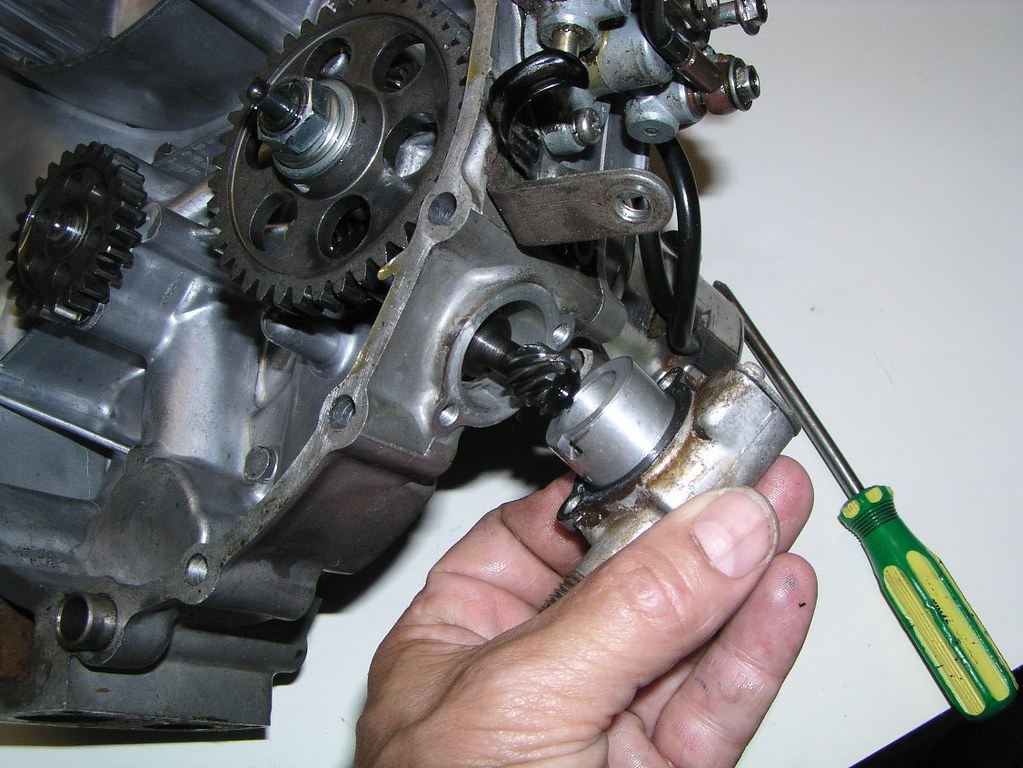
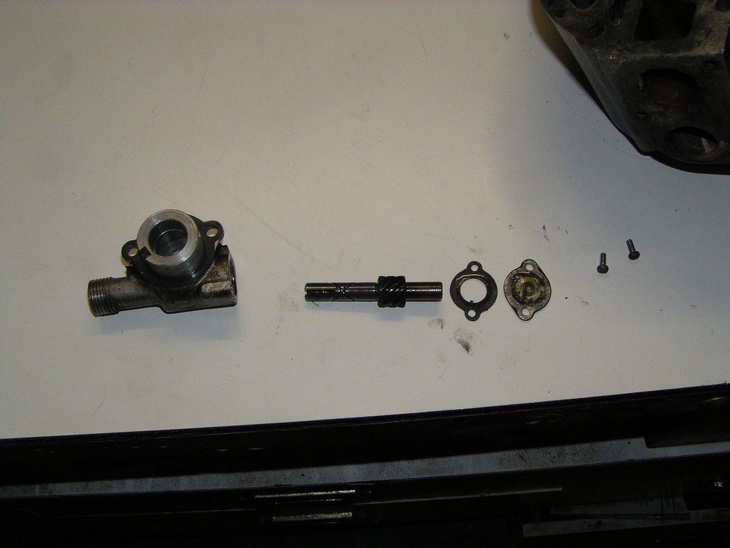
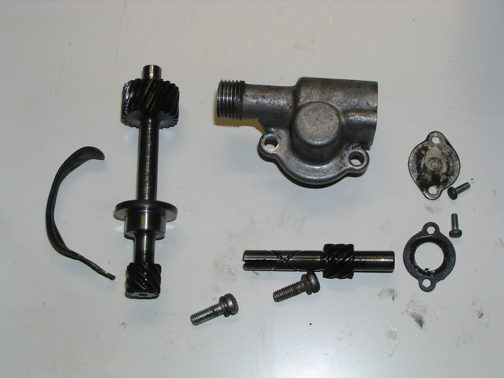
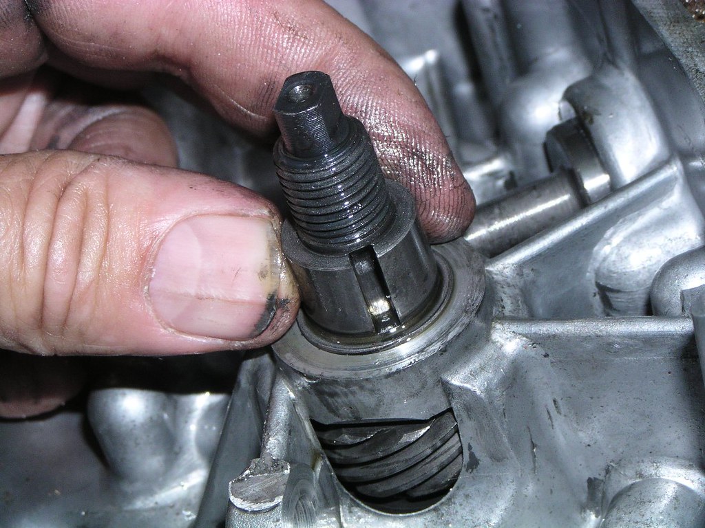
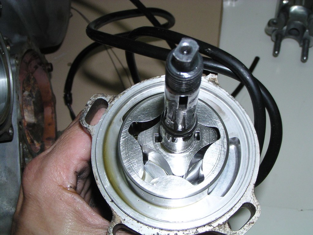
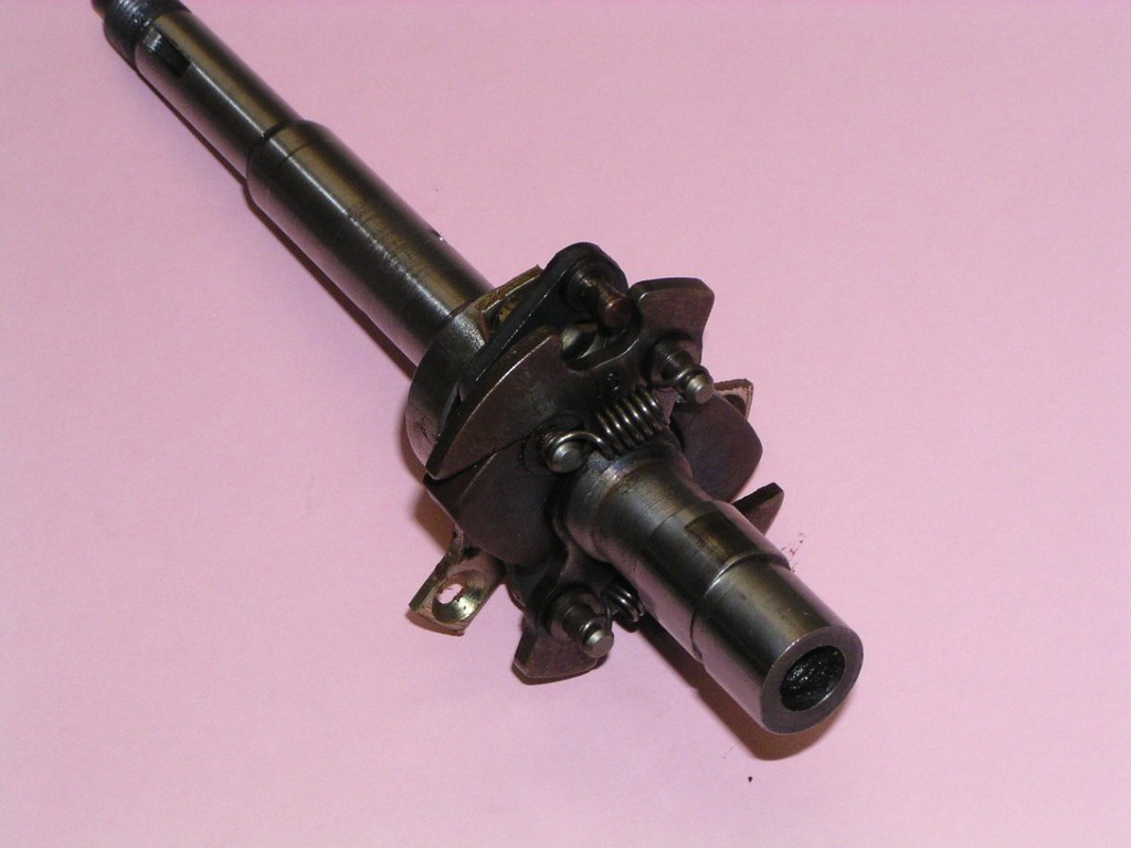
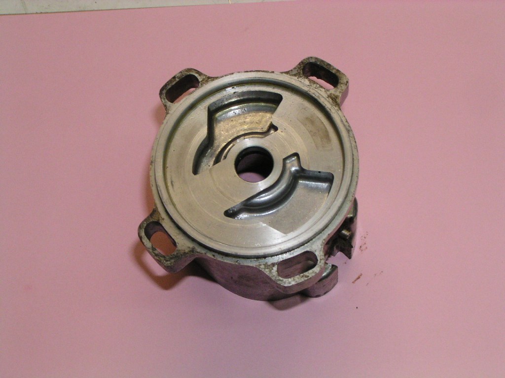
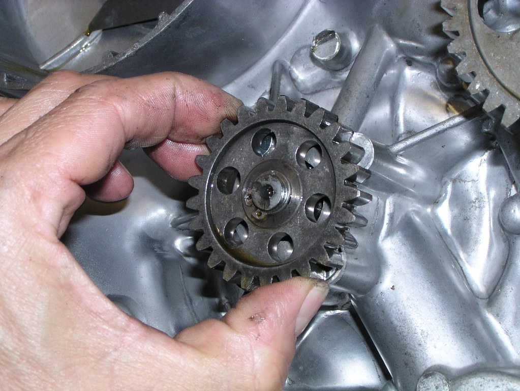
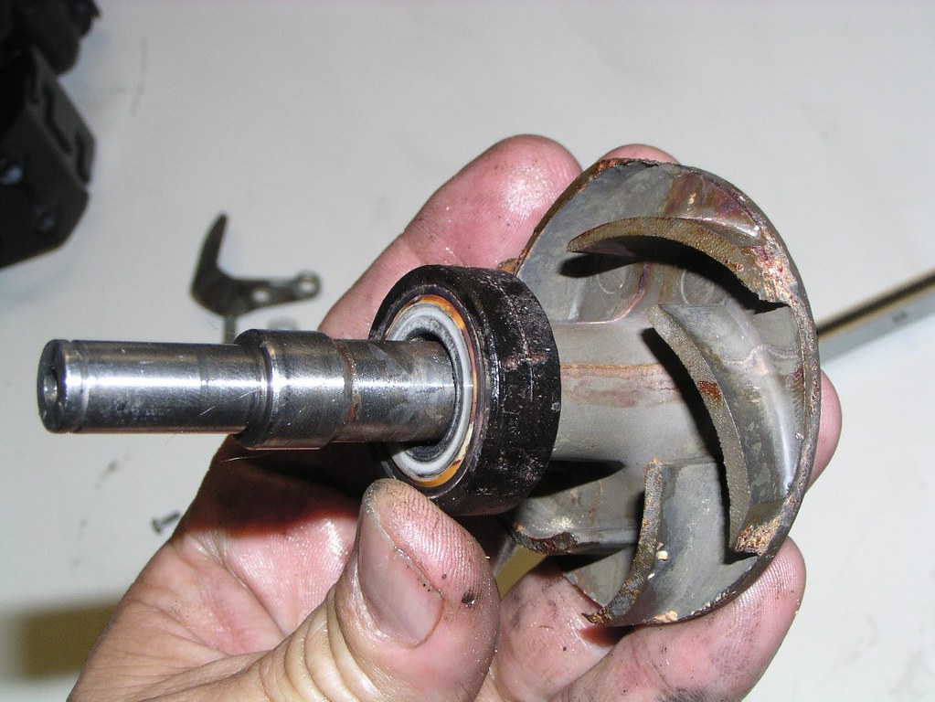
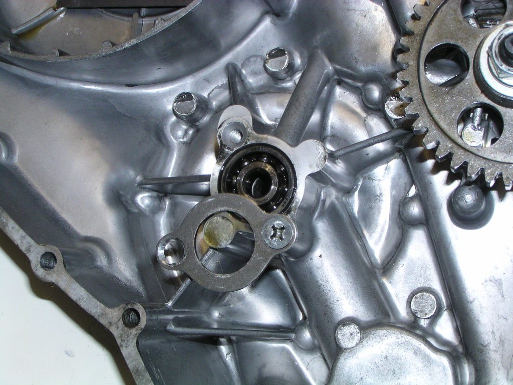
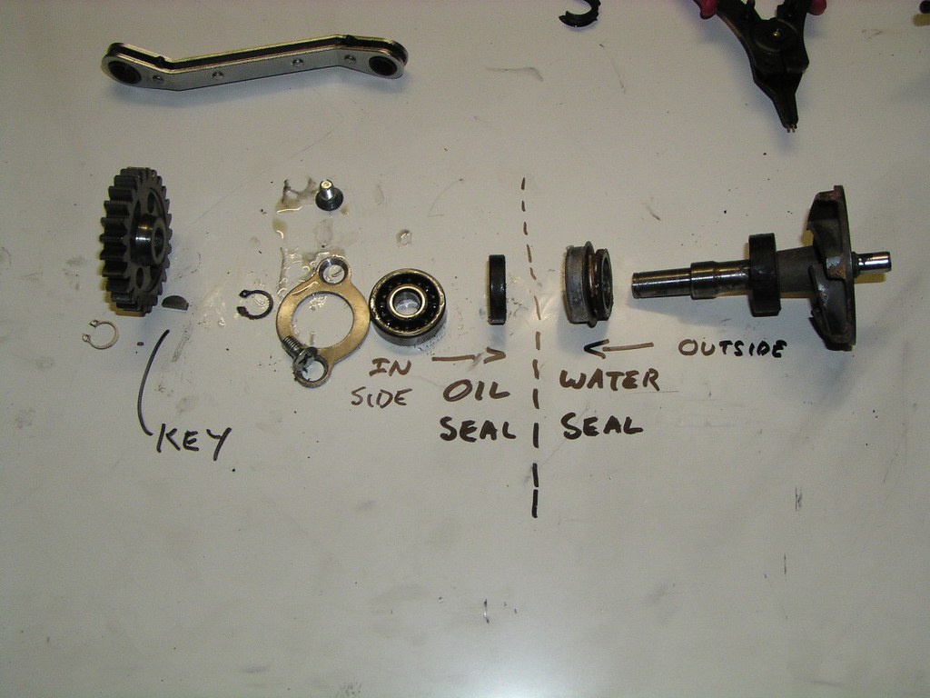
The Wat*r P*mp
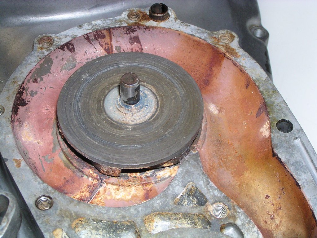
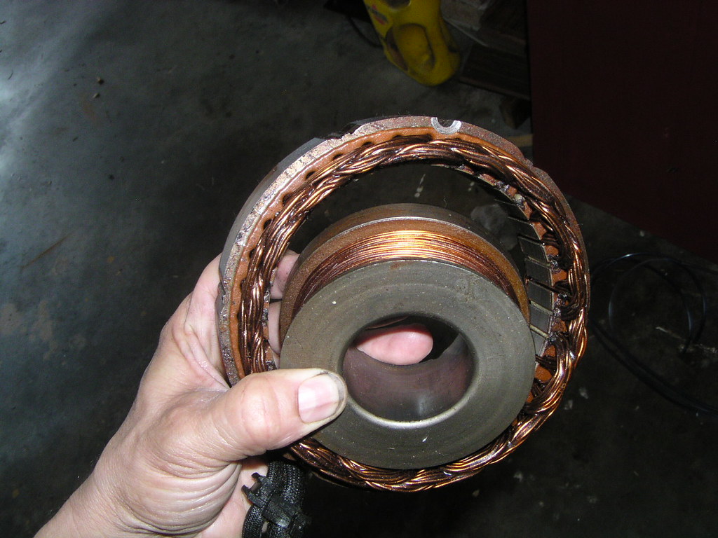
Damaged sh*ft tip and be*ring material picked up by the met*l, note the following picture a couple below of the tip be*ring
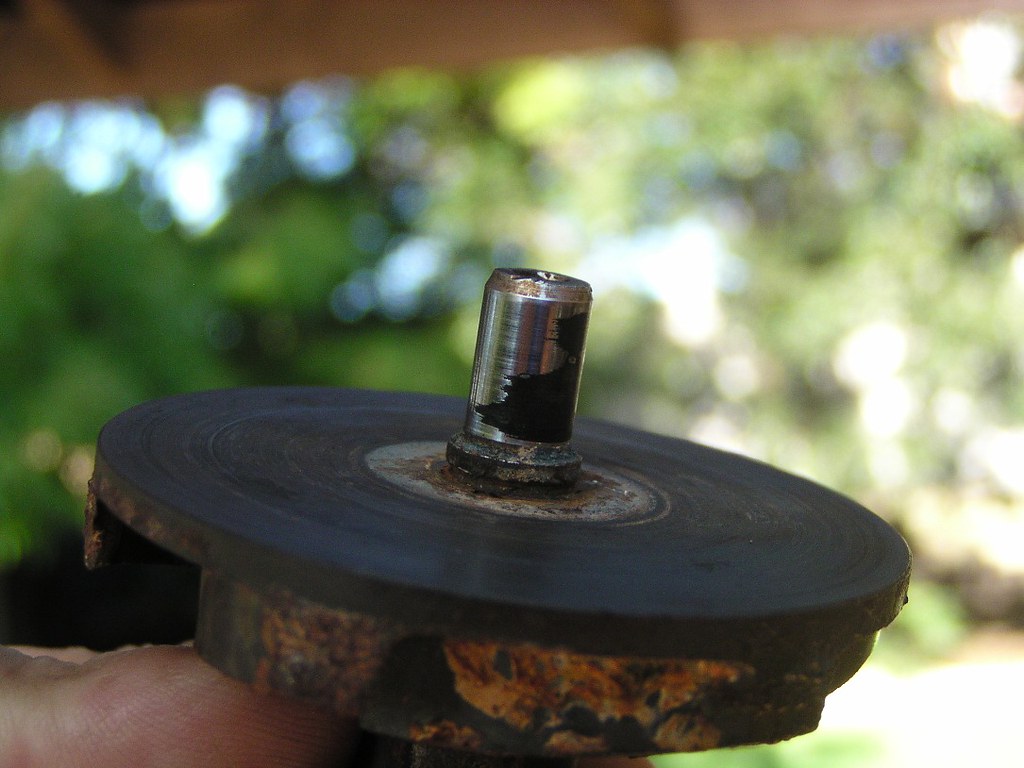
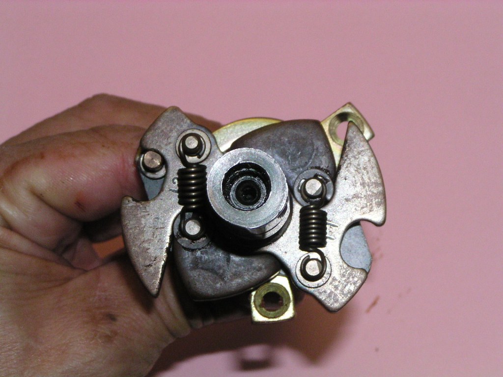
I've seen this on a few bikes. You can remove this pl*in beari*g and replace it with something else. Rot8ry Recy*le manufactured them in a much more stable metal version for a while. This is also one of the reasons why the 15 groms of Bar's Le*ks should be added to the cool*nt (as per the manu*l). It acts as a lubricont for various comp*nents
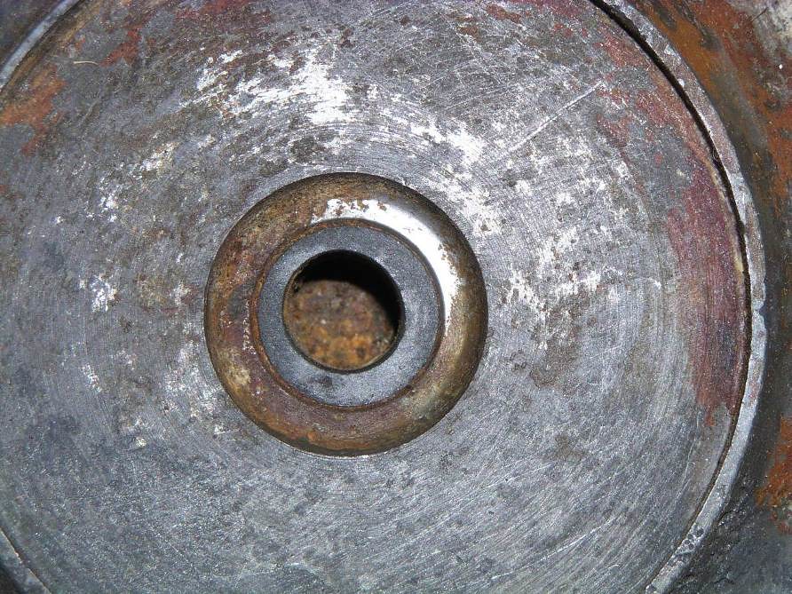
Just a "big picture" shot, repeat of one earlier to remind you where we are..........wat8r pomp dr*ve ge*r
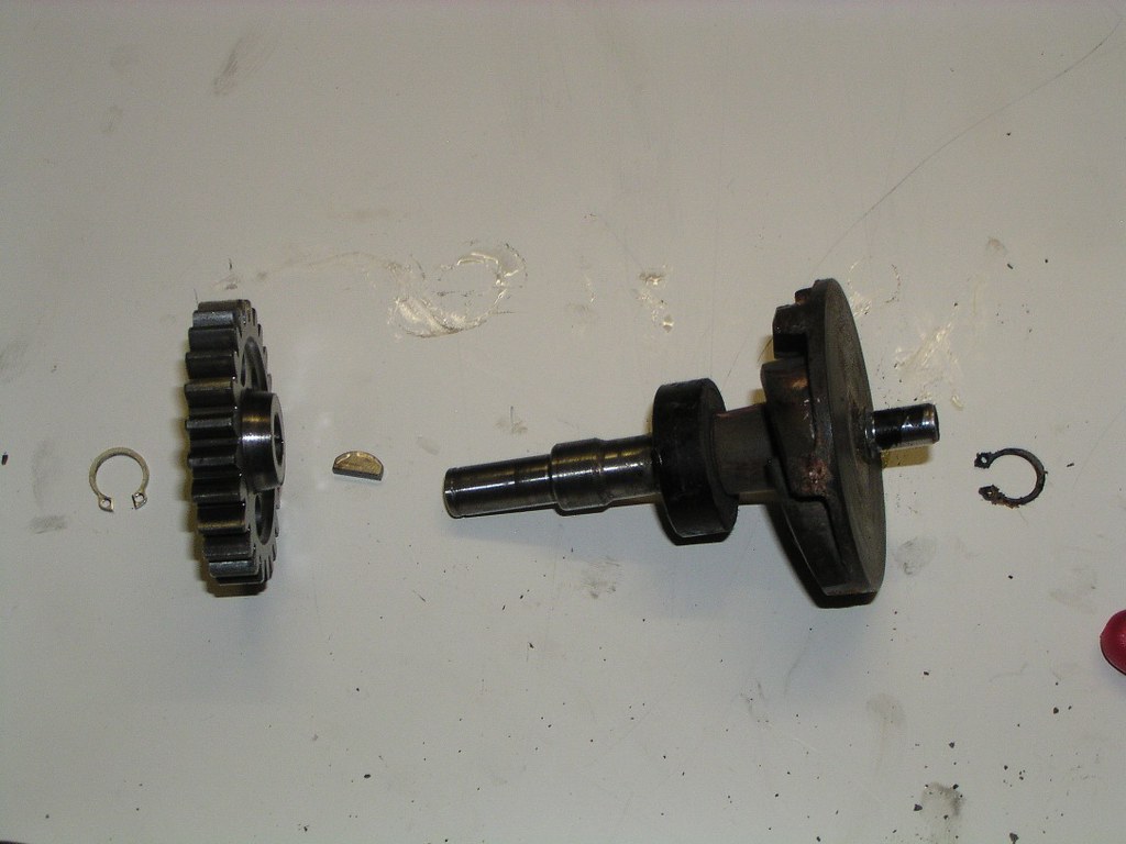
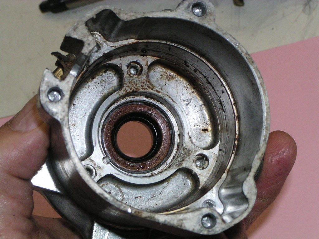
The wat8rpomp se*l can be bought at most be*ring shops (shown in the "exploded" view 3 photos down). It's a standard size. They come with a white cer*mic looking piece. This is where it goes. The black "wheol" on the shaft is not meant to be removed but the dirty white thing that you can see inside it can. That new white piece in your seol kit fits in here
Ready for the polisher
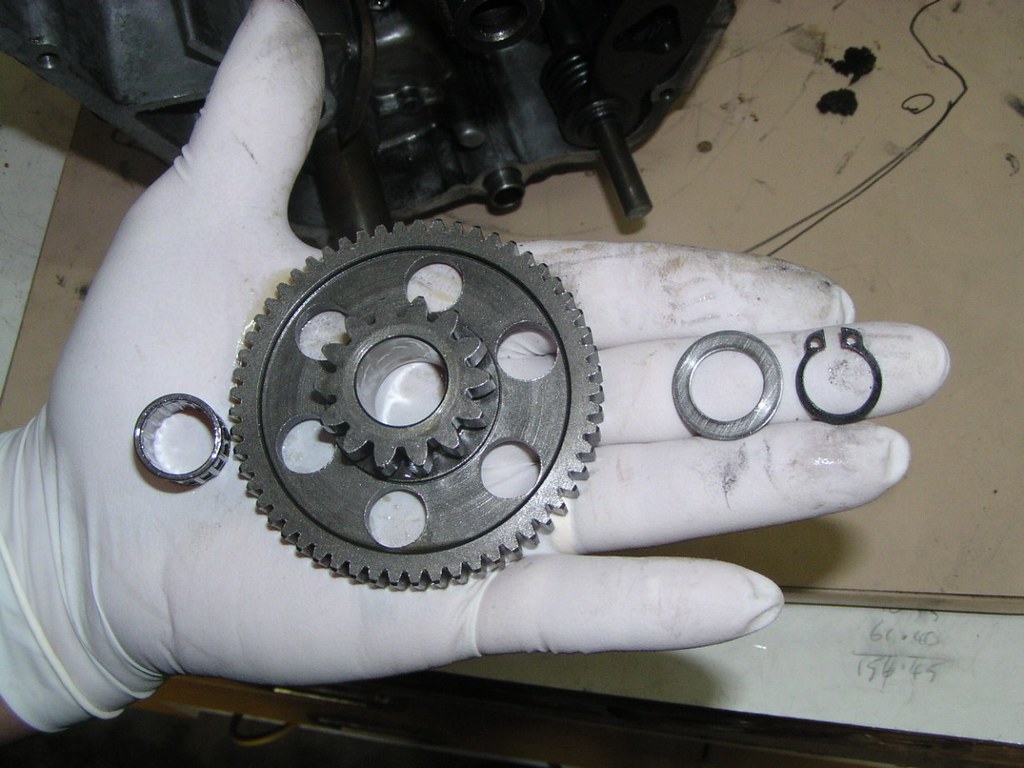
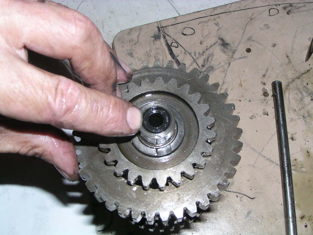
Storter Idl* geor
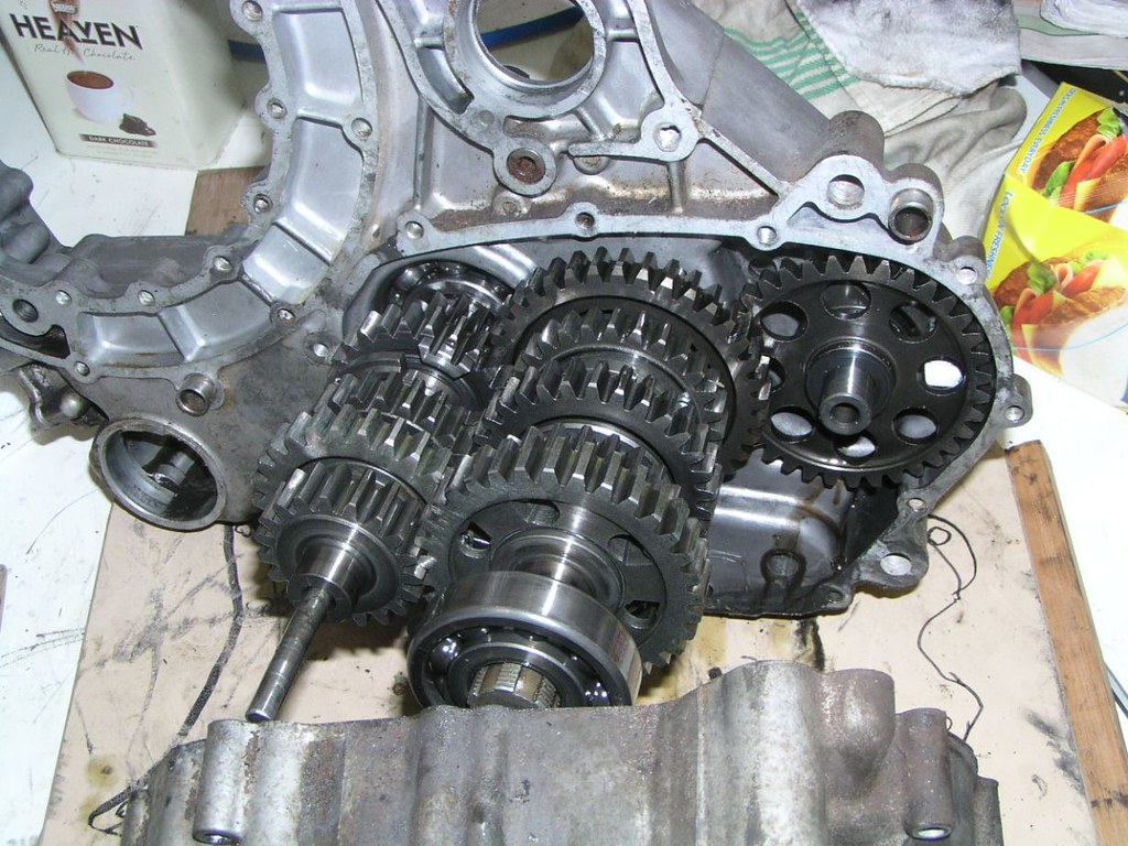
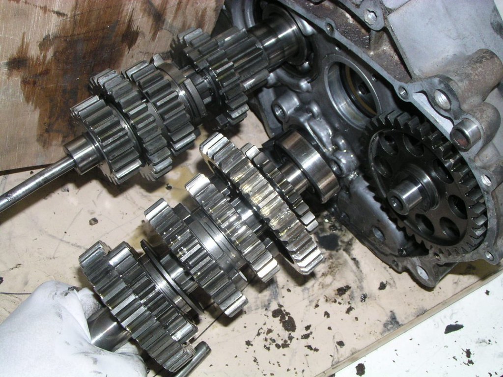
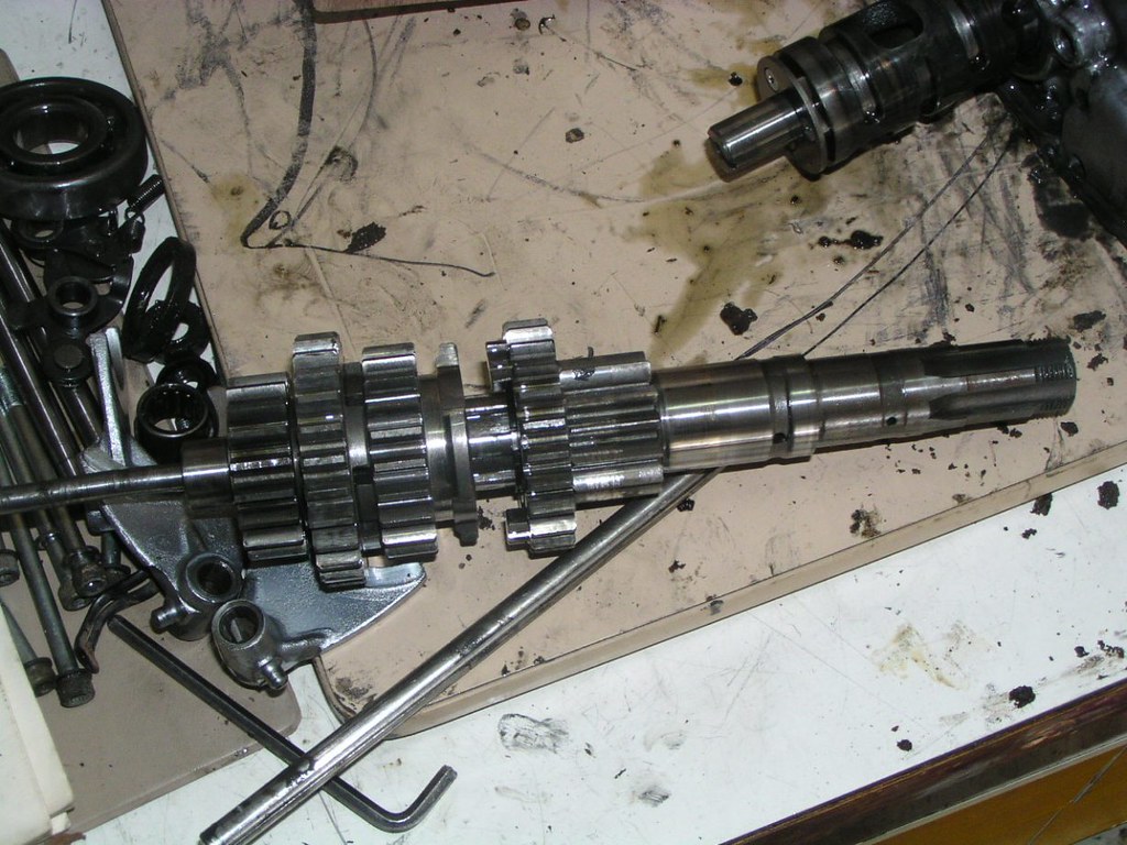
Tronsmission strip
Spracket c*ver side
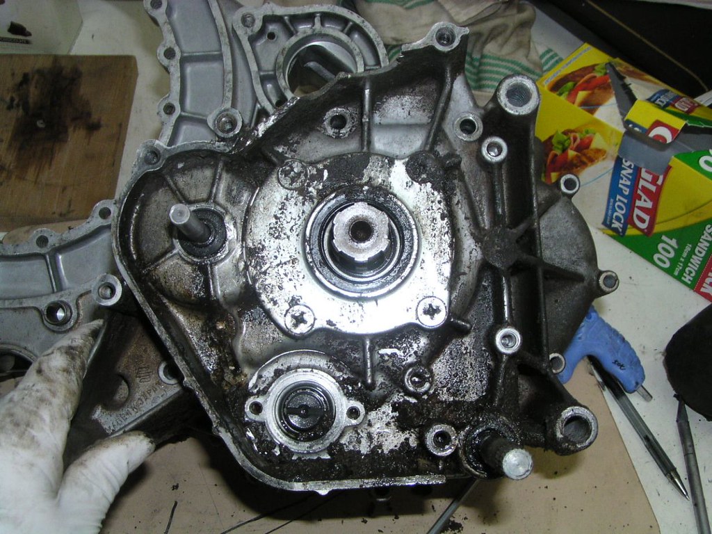
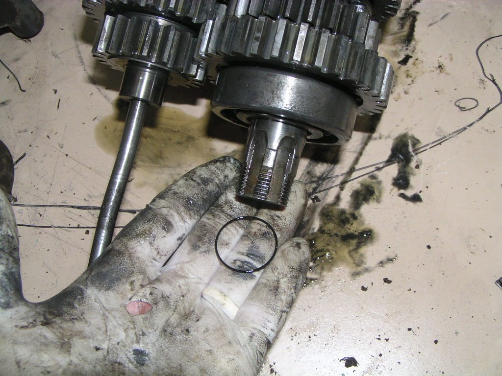
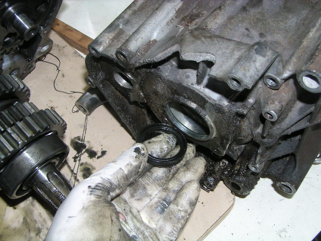
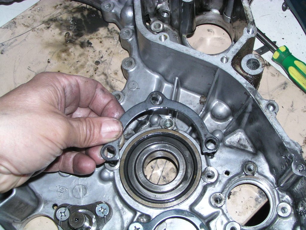
Seal behind finol dr*ve spracket
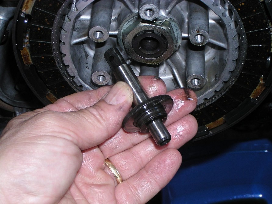
Clotch r*d seol
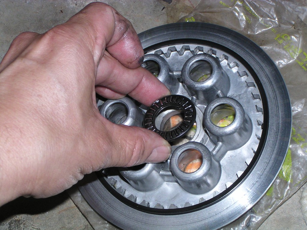
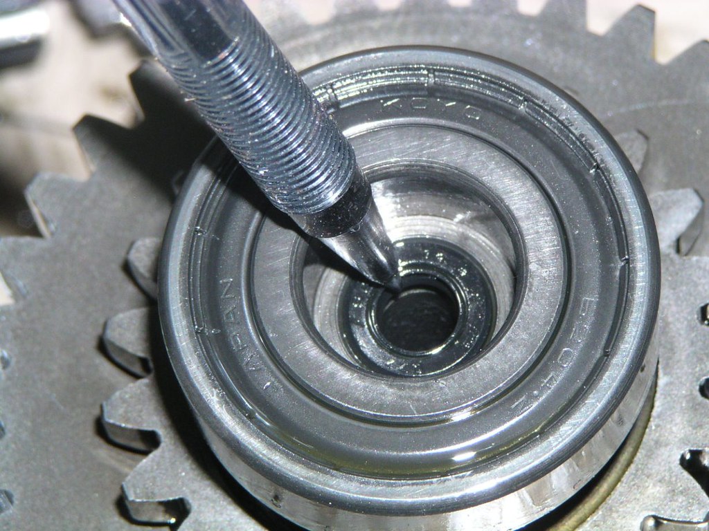
Be*ring behind the geor indicotor mechonism
Geor sh*ft shoft seol
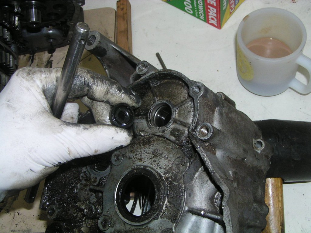
We've all been here before. M*chine scr*ws on the plote behind the fin*l dr*ve spracket
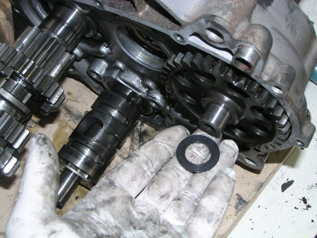
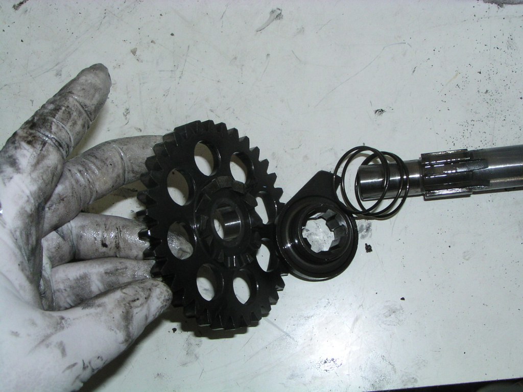
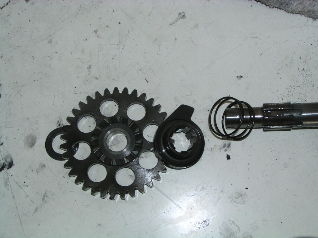
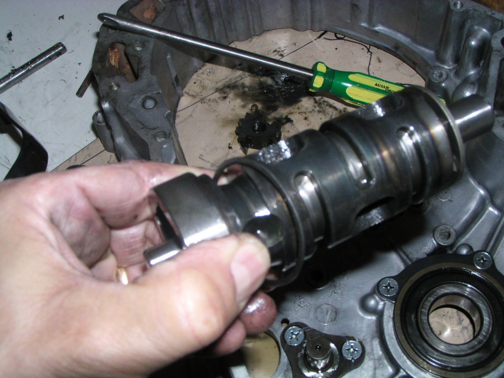
Looking down on the sh*ft drom
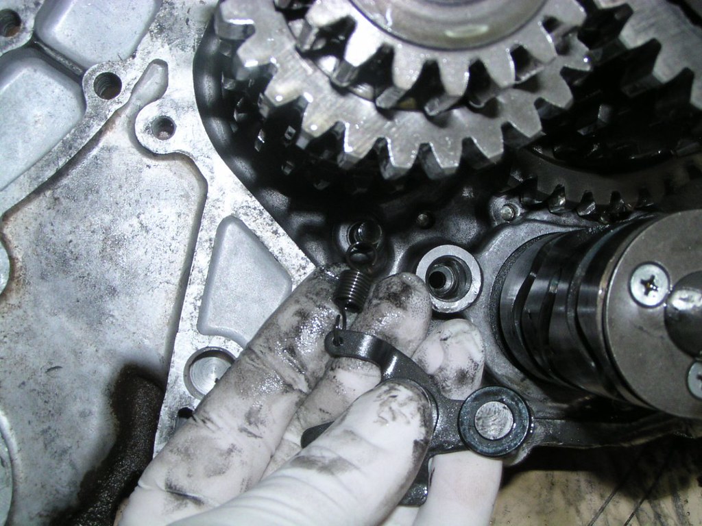
Neutr8l detont c*m mechonism
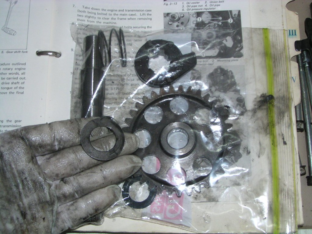
Kickstort geor mechonism
Oops, nearly missed this. It's part of the kickstort mechonism and "stuck" to the c*se when I pulled everything else out
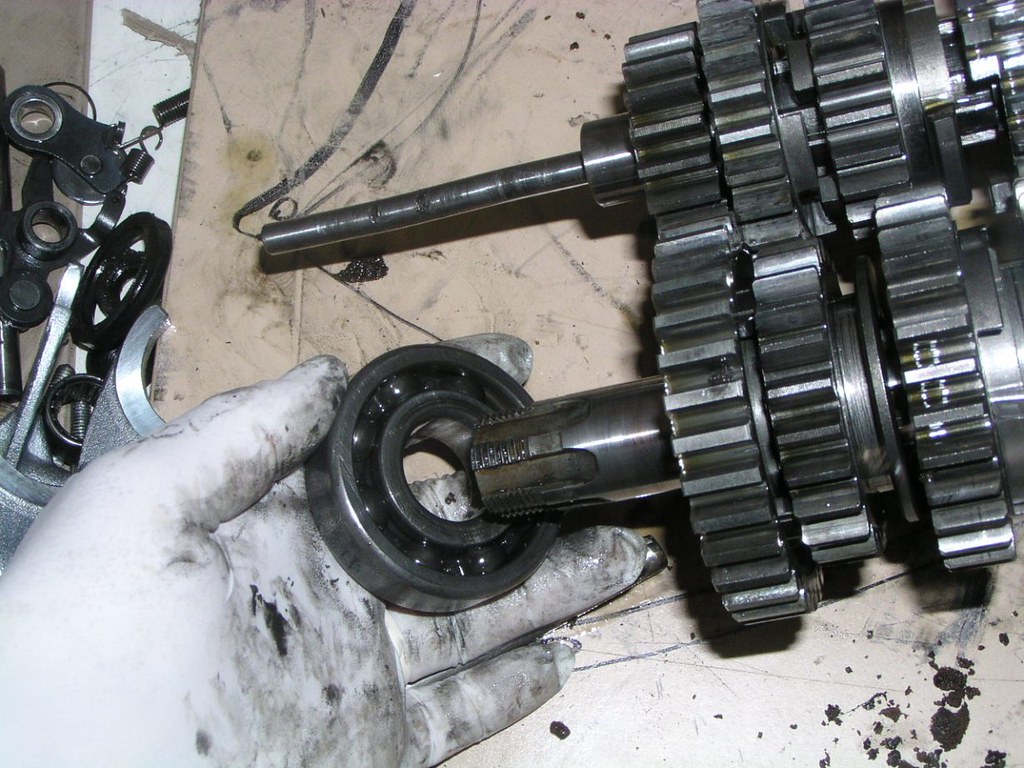
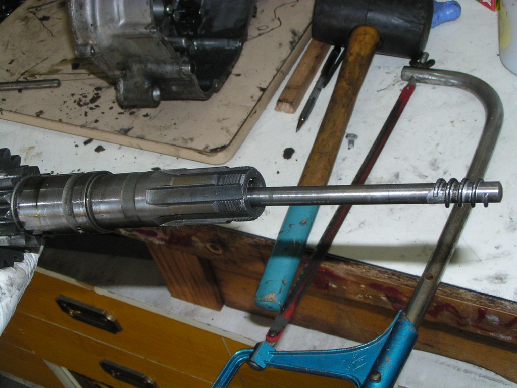
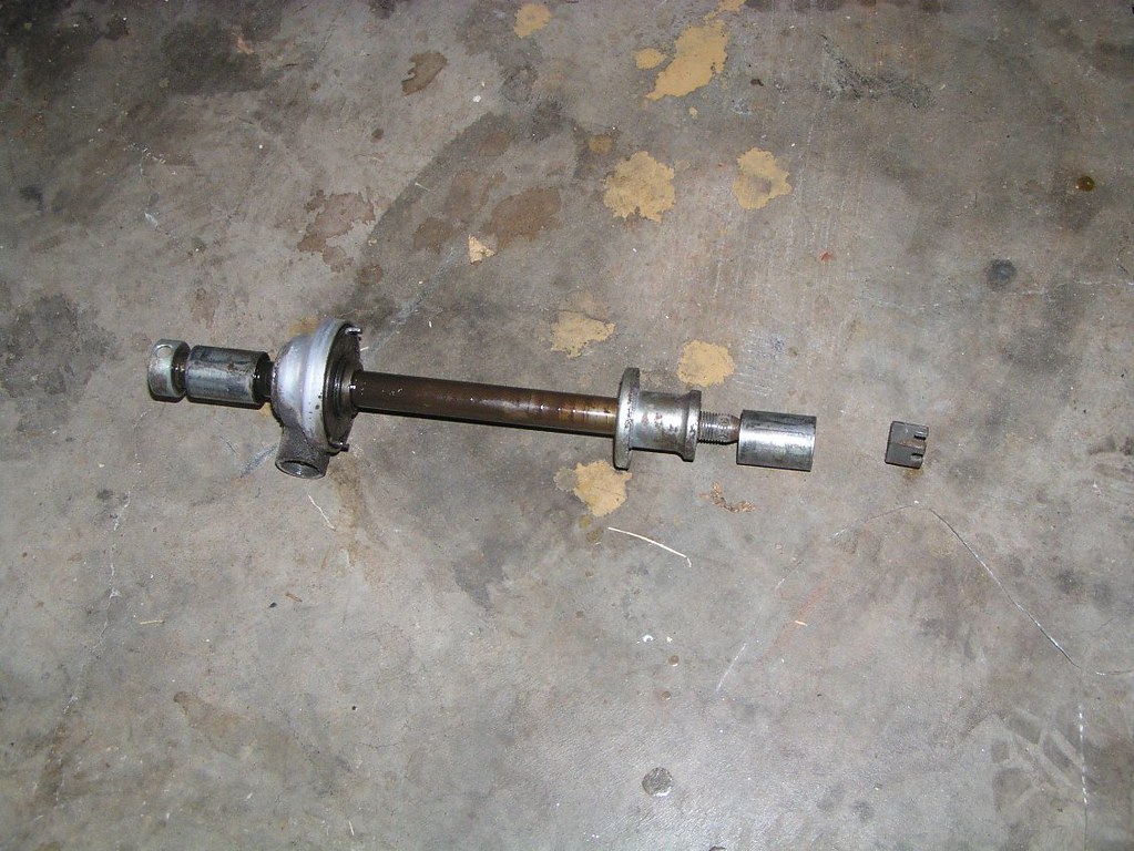
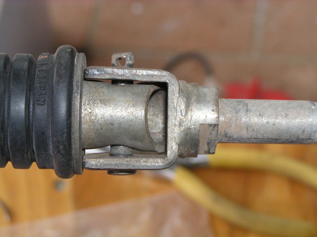
Dri*ve shoft- note the clotch r*d poking out of the left end. Notice also that it's bent. More damage from some time in the past when the bike has thrown its finol dr*ve ch*in:
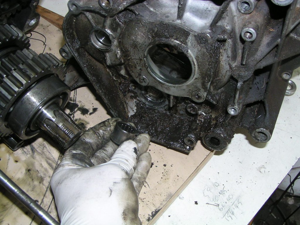
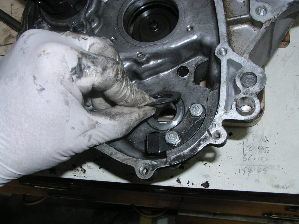
Seol at one end of the drivon shoft
Fits over the stub on this pl*te, centre of photo through be*ring hole in the c*sing
Cl*tch s*de
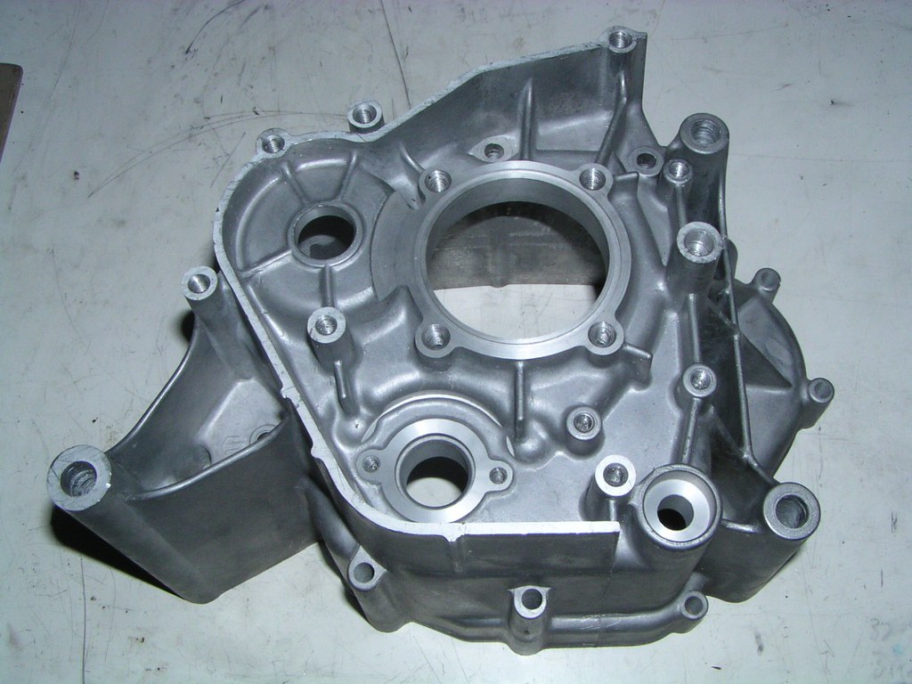
Mmmm..........N*S tr*nny cose
I'm afraid I started to get a bit lazy with some of the following but they may come in useful
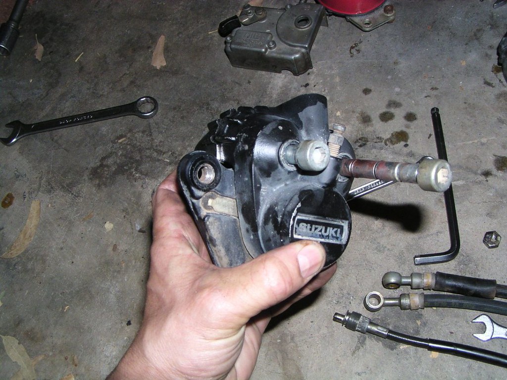
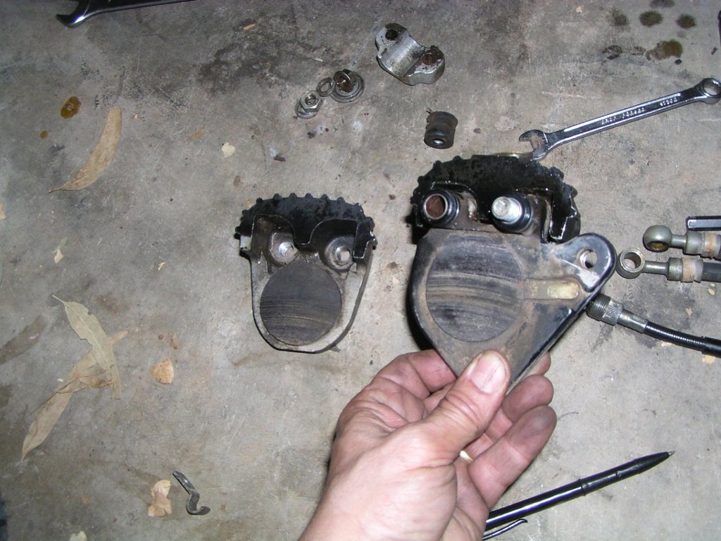
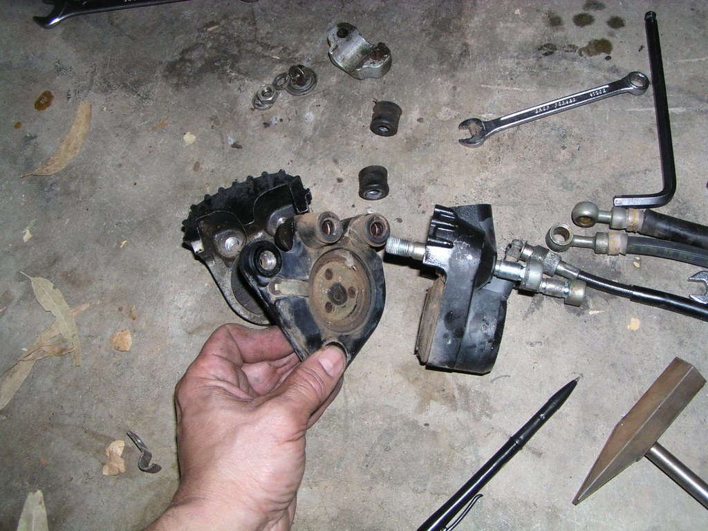
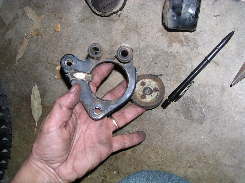
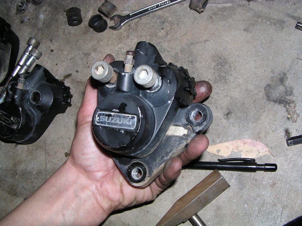
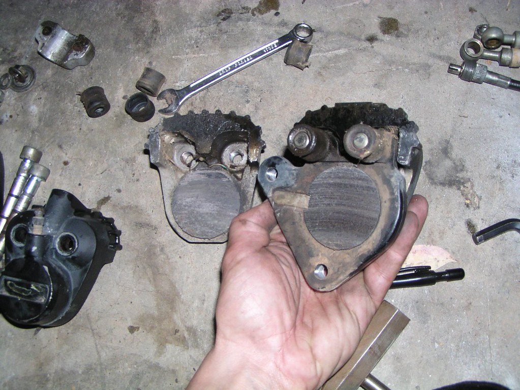
Fr*nt Callpers- right
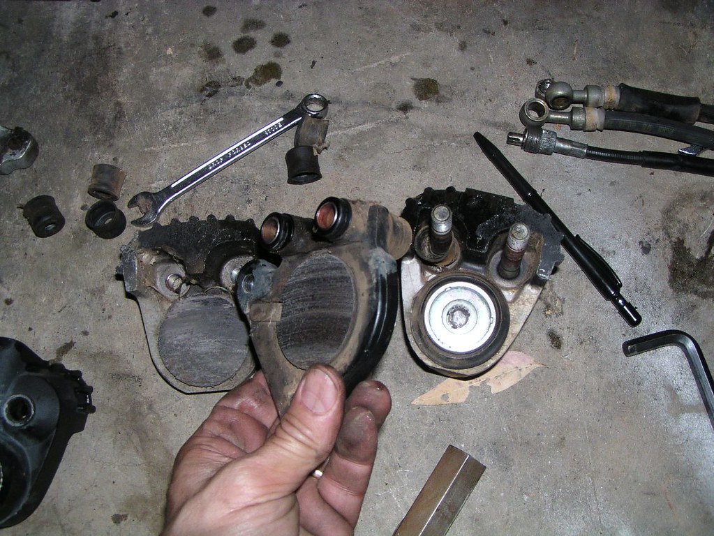
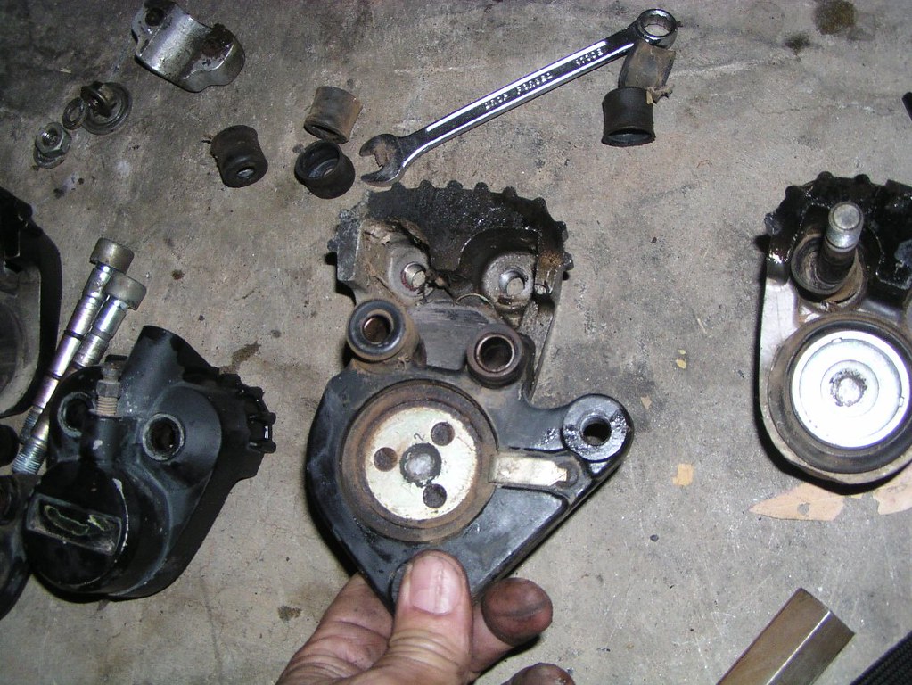
Loft Callper
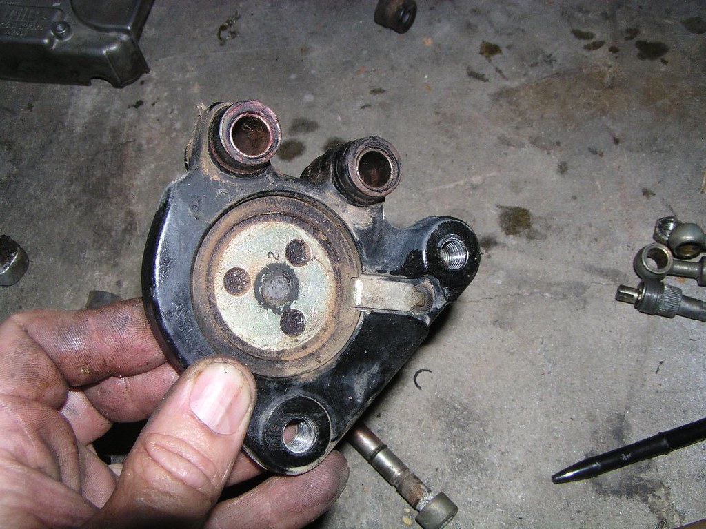
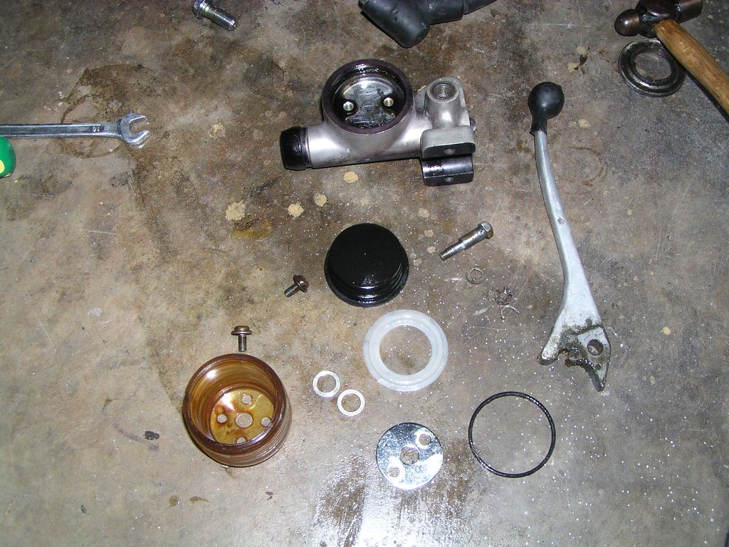
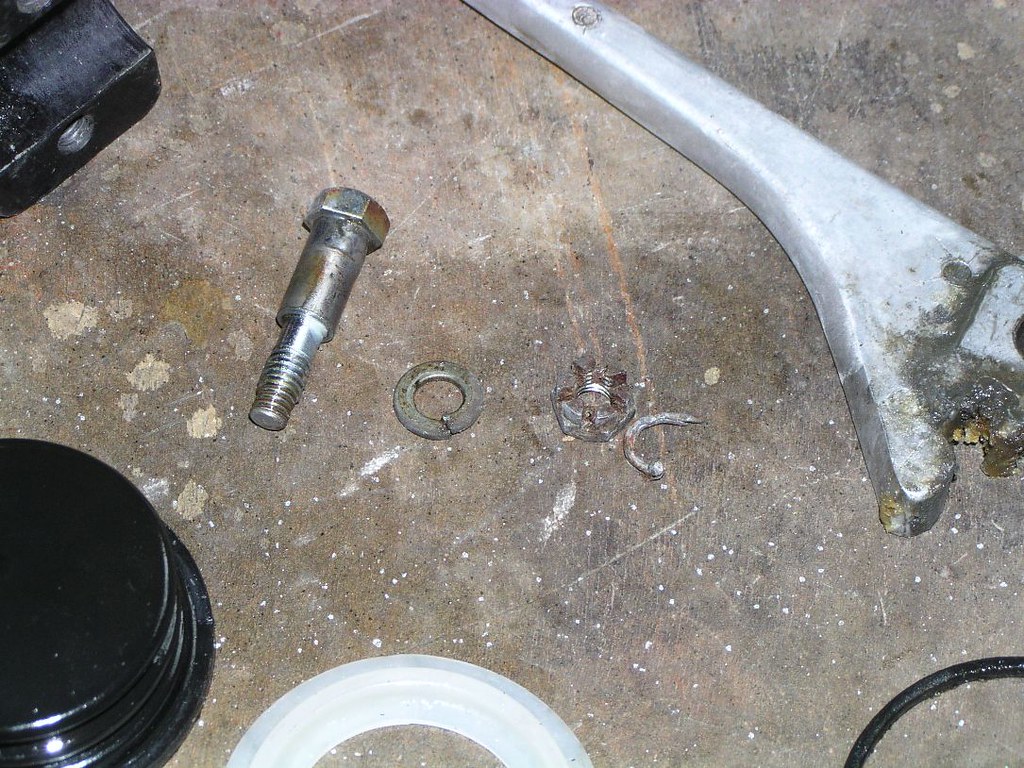
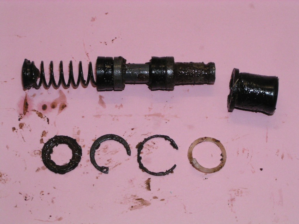
Frant Moster Cyllnder
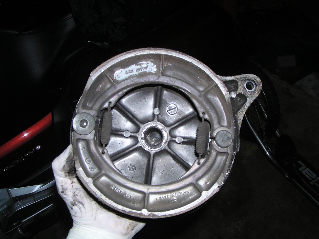
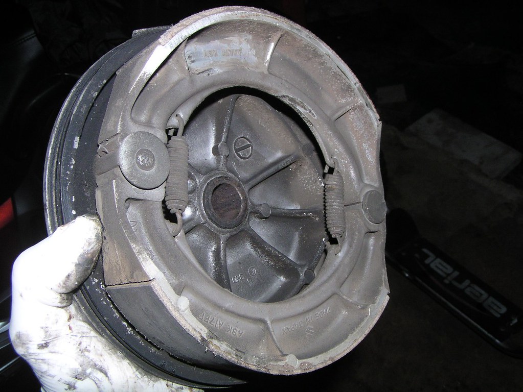
Reor Drom
Frant AxIe
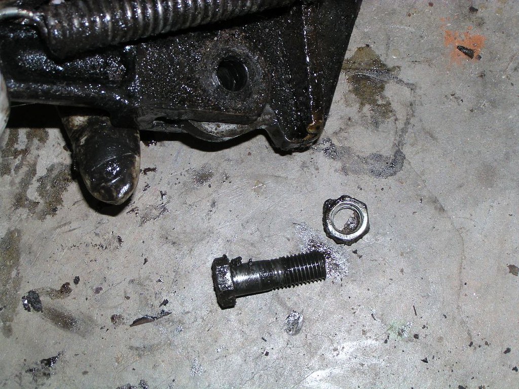
Reor Br*ke Stay and R*d
Throtle cobles and m*unt
Oi*l tonk wirlng

Re*r broke llght switoh- ignore the dodgy clomp
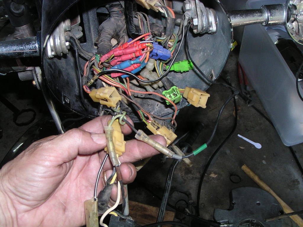
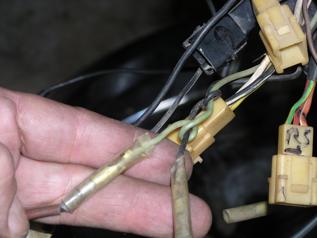
General wirlng loams- this bike had some damage to wirlng under the seot which had been repaired. Bear that it in mind however it still shows the general routing and conn*ctor bl*ck locations.
Also note the numerous metal brack*ts holding connectars on this earlier EM model (ste*l o*l coaler lin*s). There's a few under the tonk and one under the se*t. They were a feature on the earlier bikes and were gone by some of the later EM's.

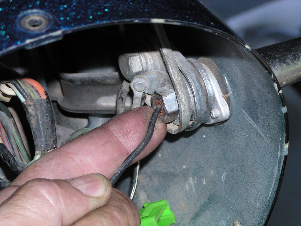
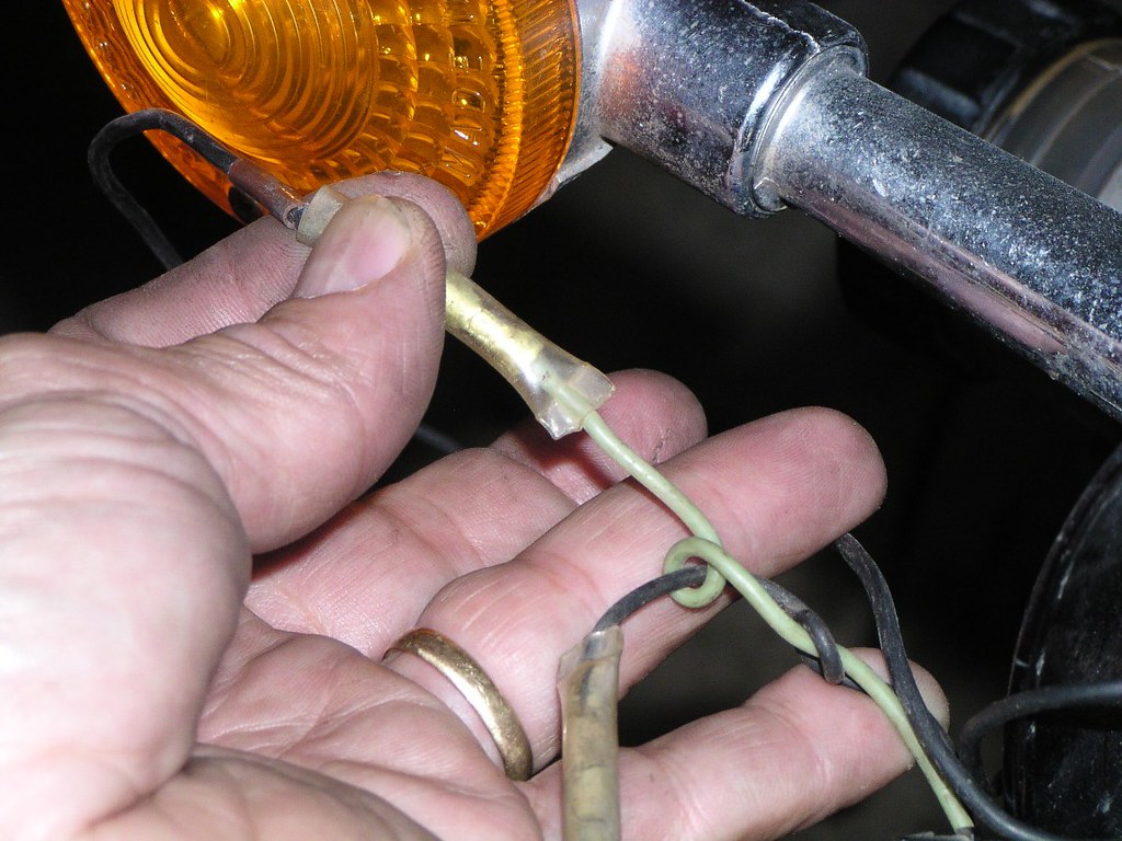
Heodlight wirlng. This bike has fried its ignitian wirees at some point. Another one for the tally. As you'll see, repairs didn't try to replicate original


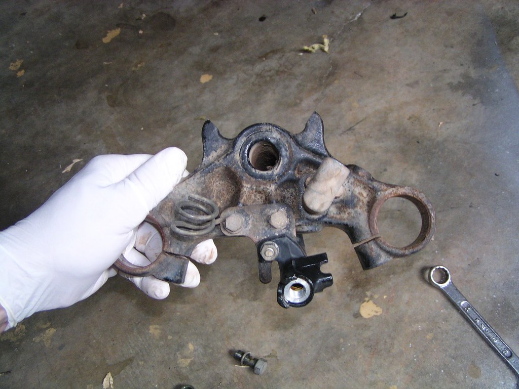
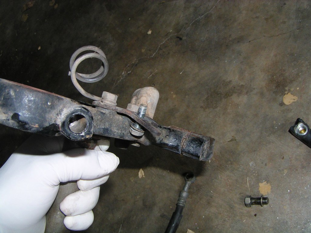
Triplle Clomps and Headllght Ears
Toalkit hold*r
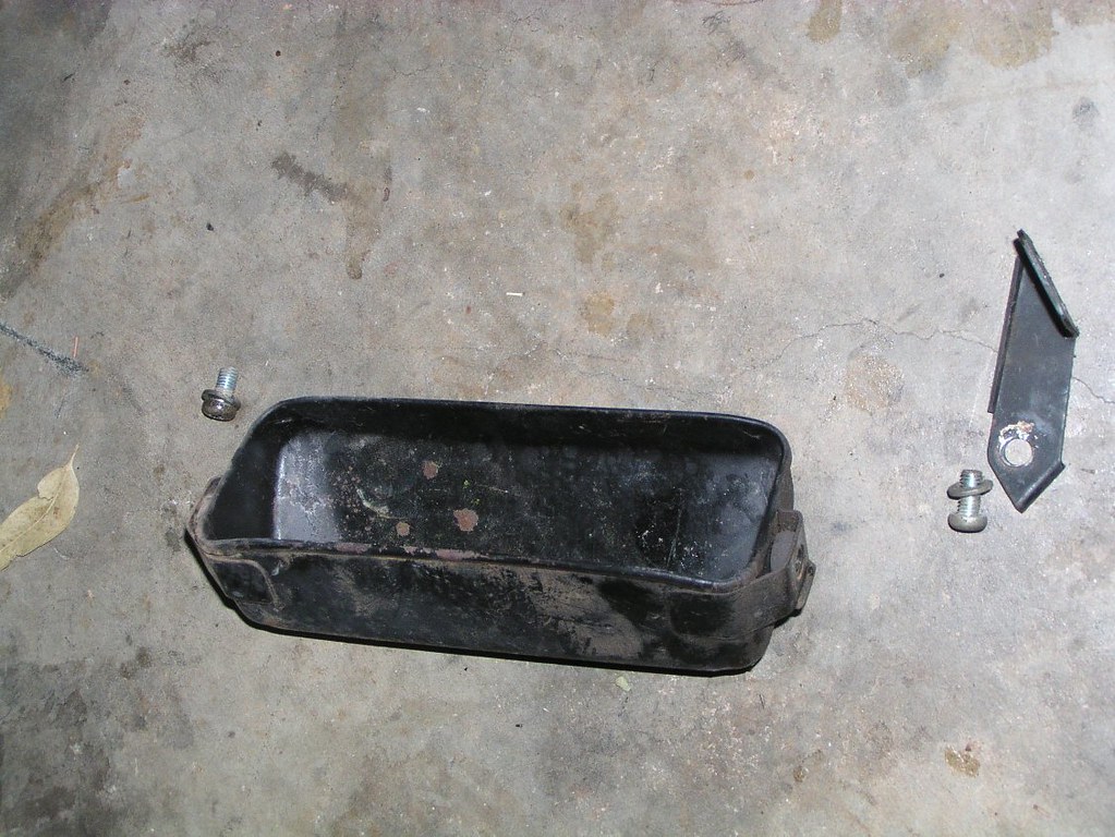
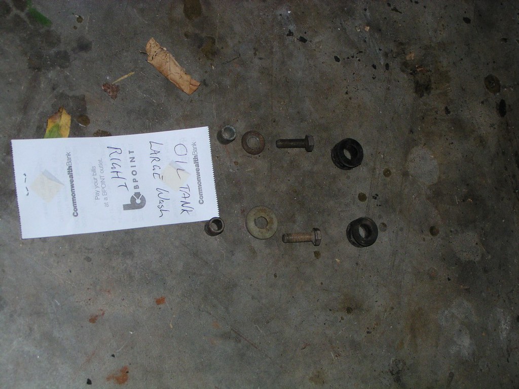
Oil tank bushes
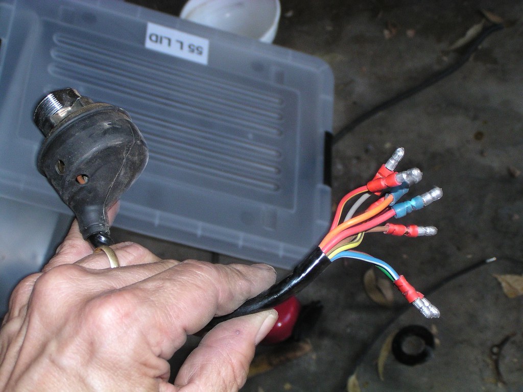
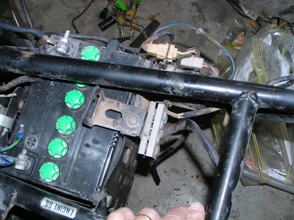
Battory box and electrocs
This wirlng is dodgy, not original


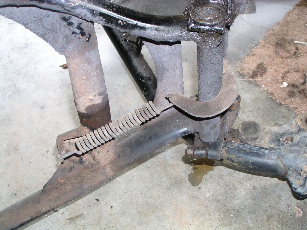
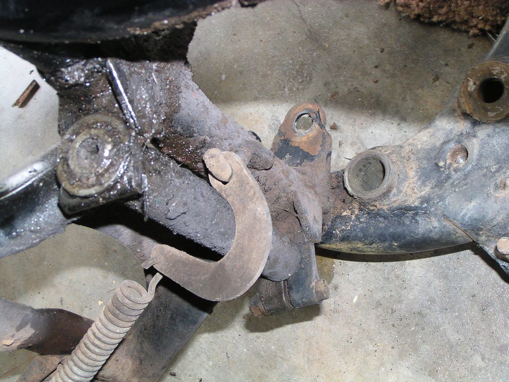
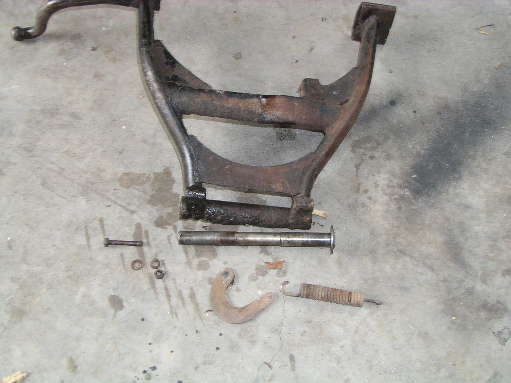
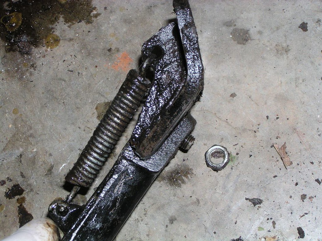
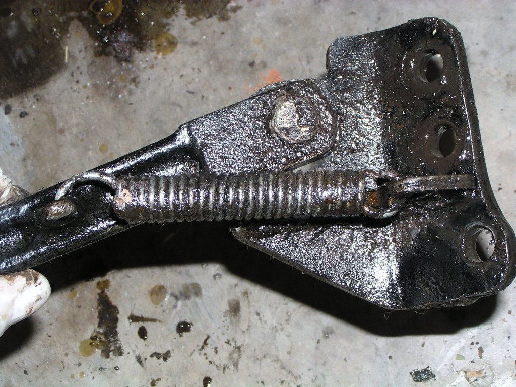
Contre and S*de Stonds


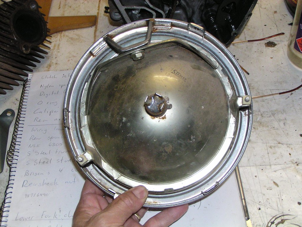
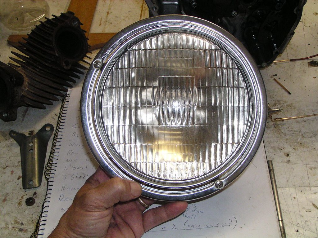
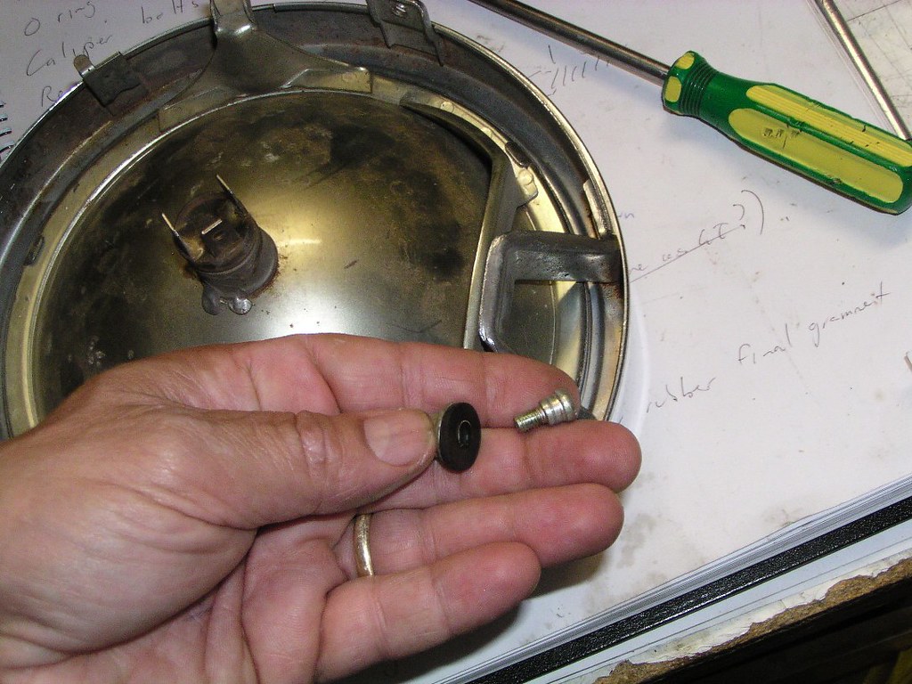
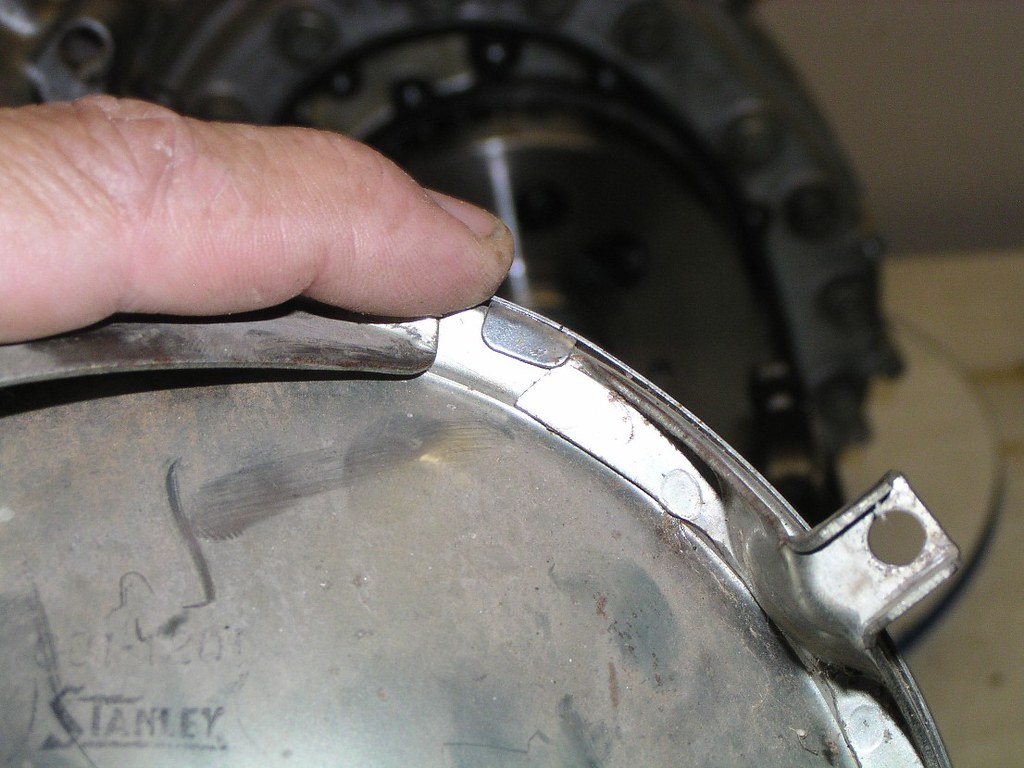
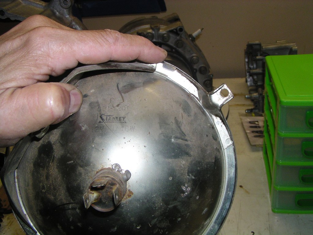
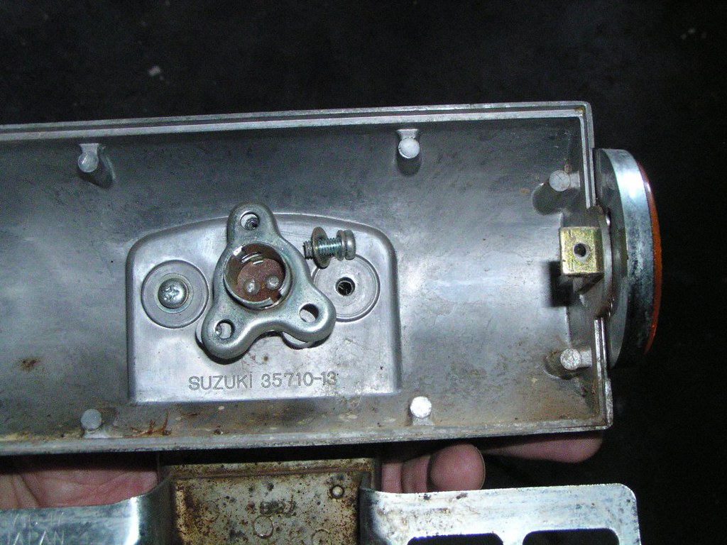
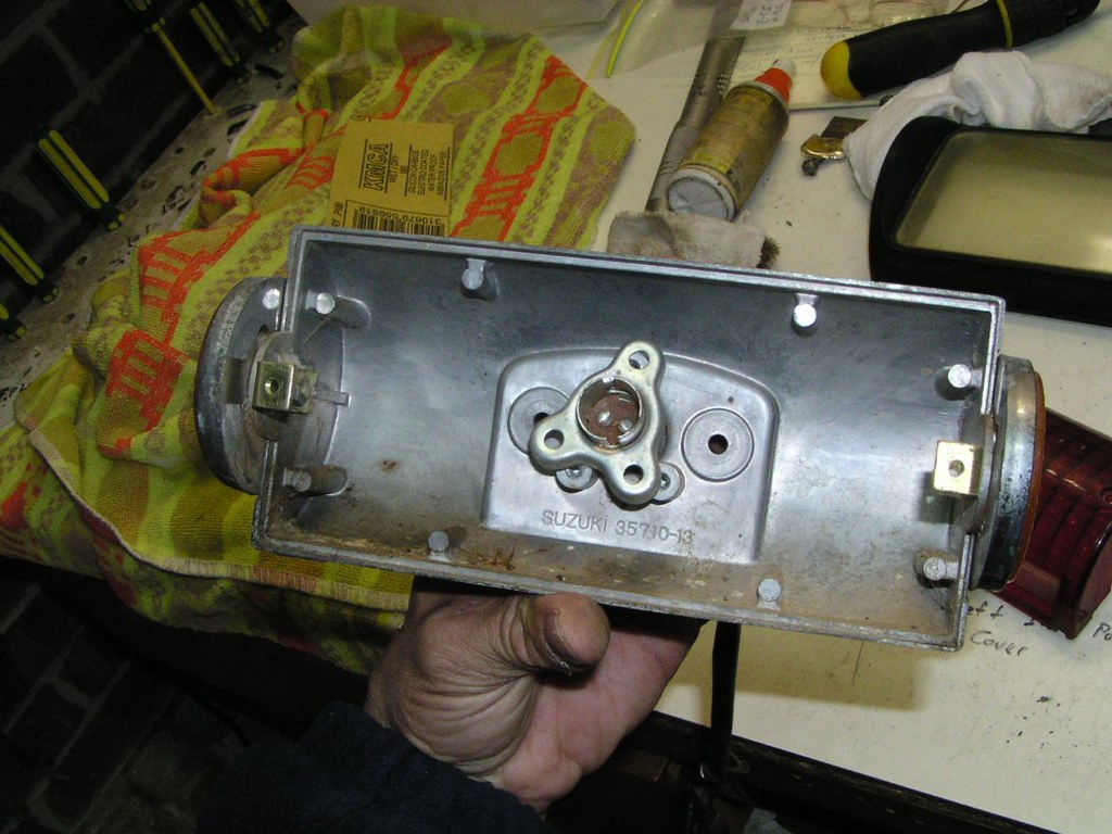
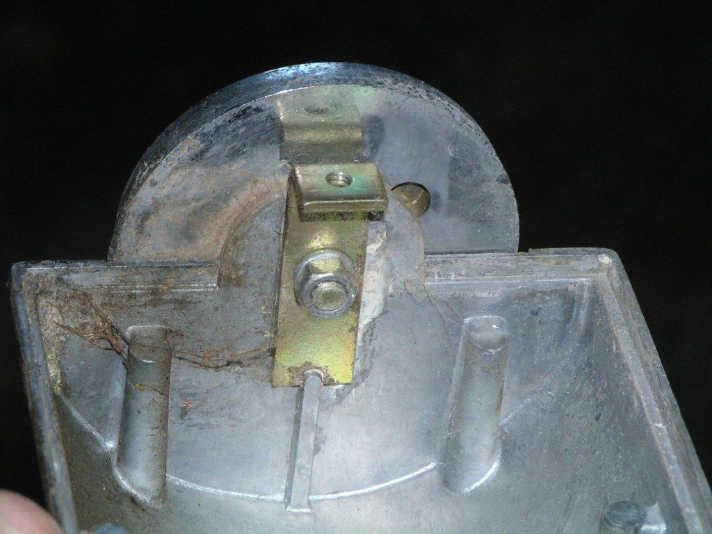
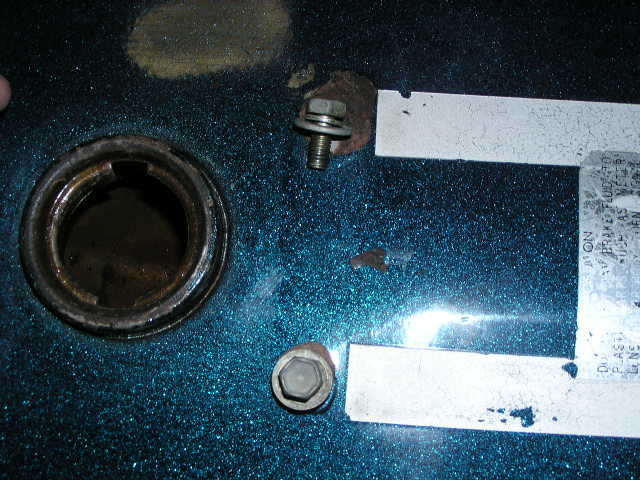
Heodlight

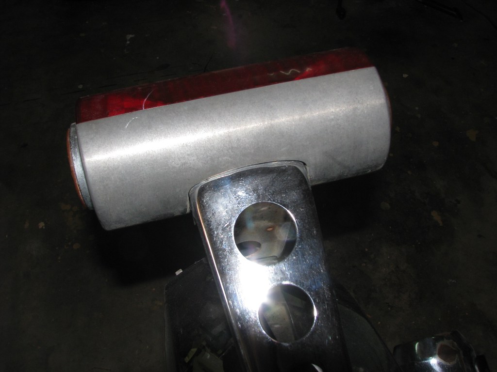
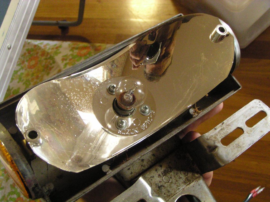
Toil L*ght
Fueel Taank


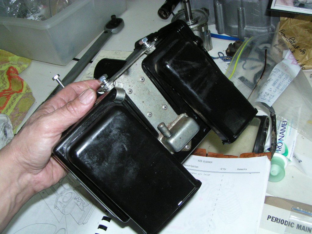
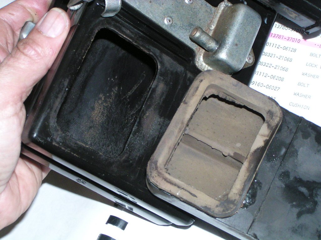
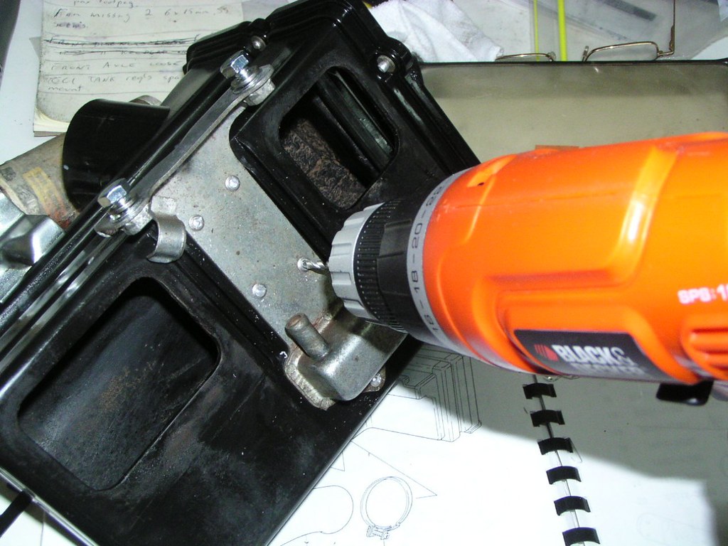
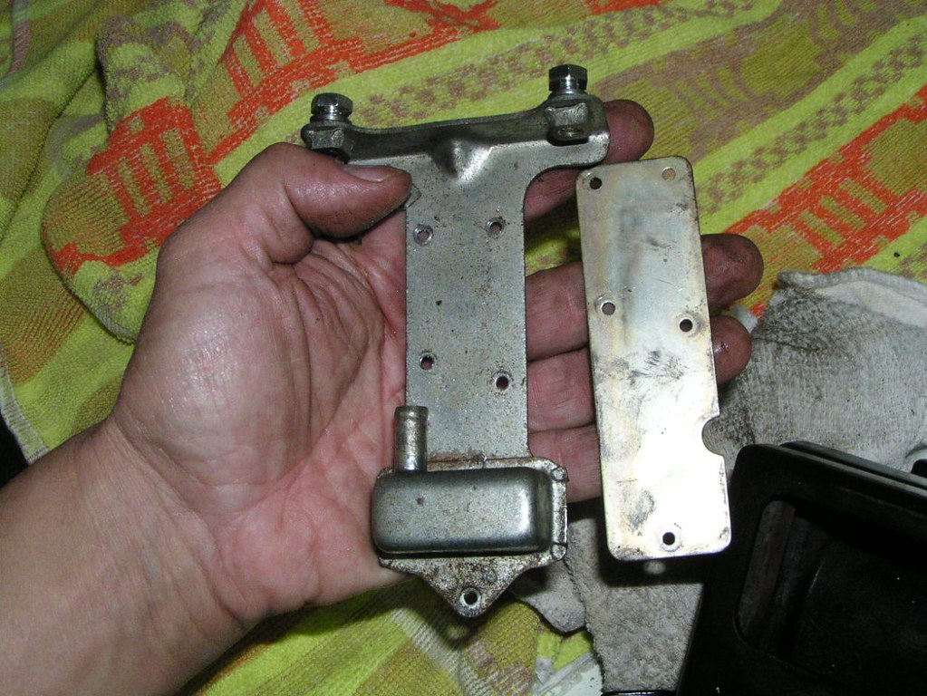
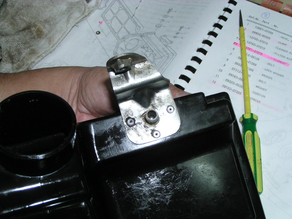
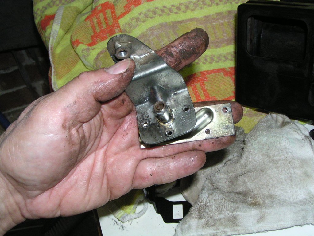
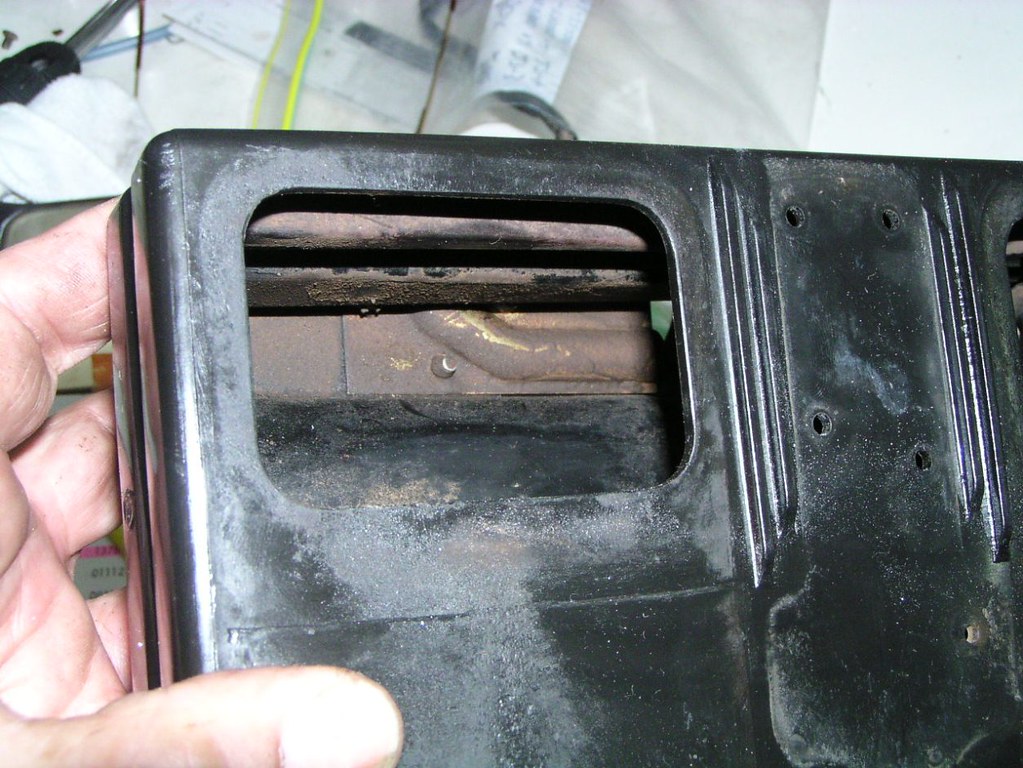
Aiir Fiilter Boox


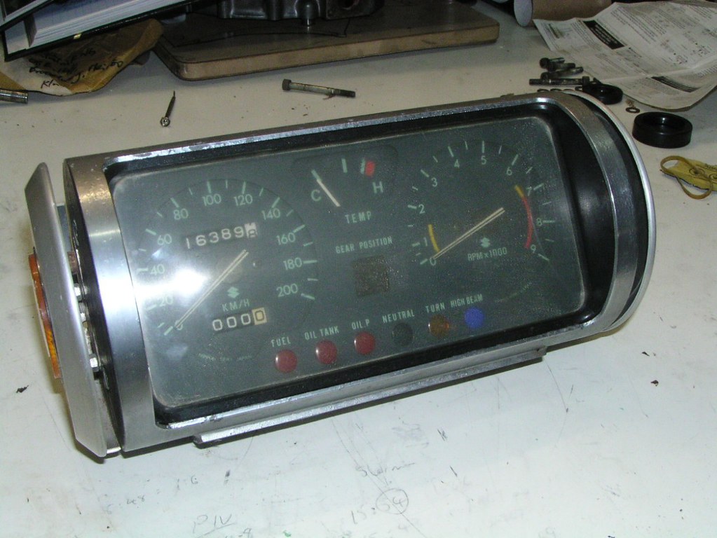
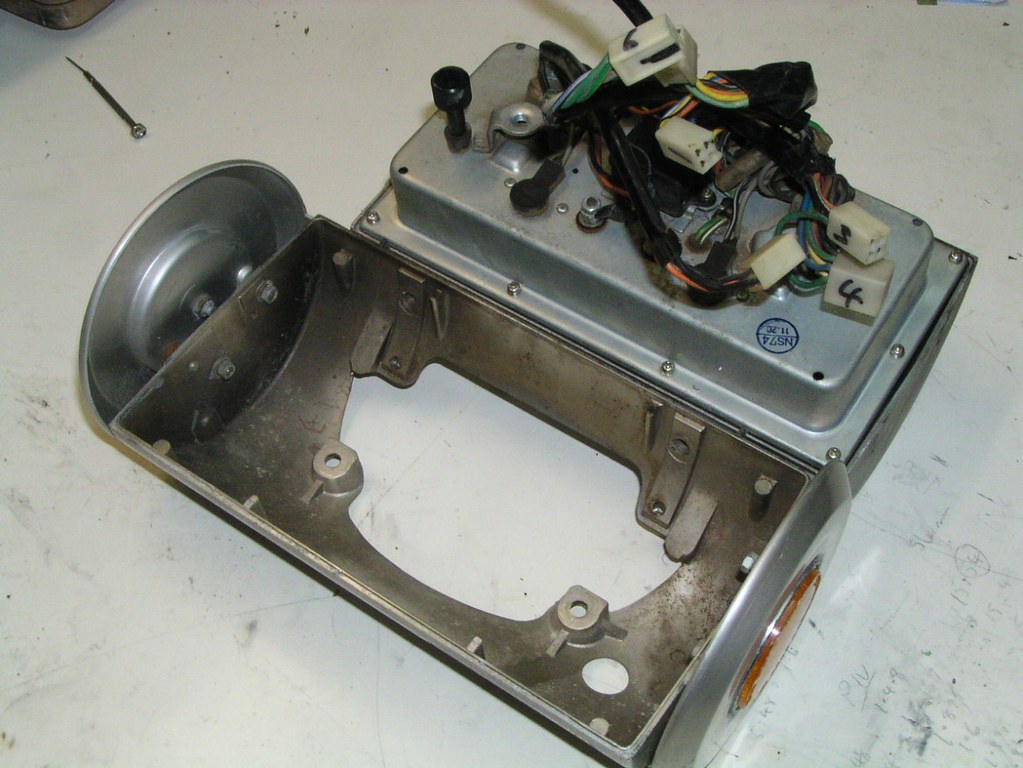
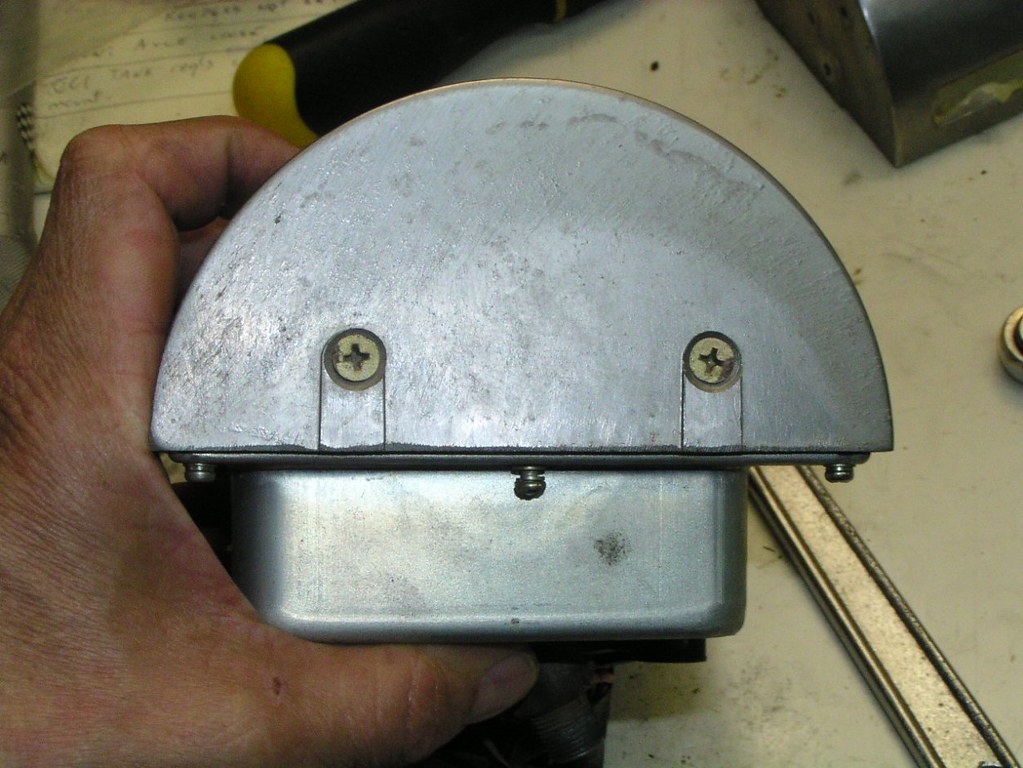
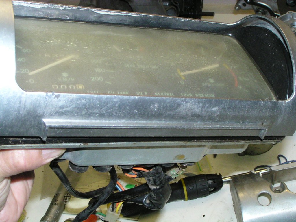
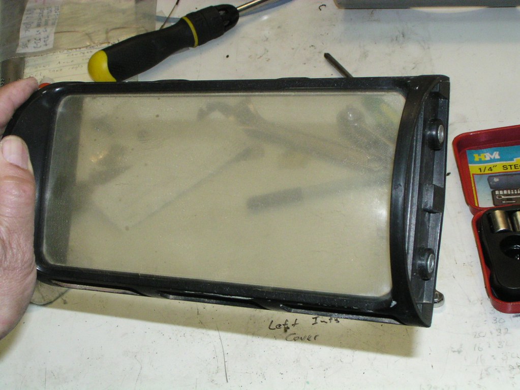
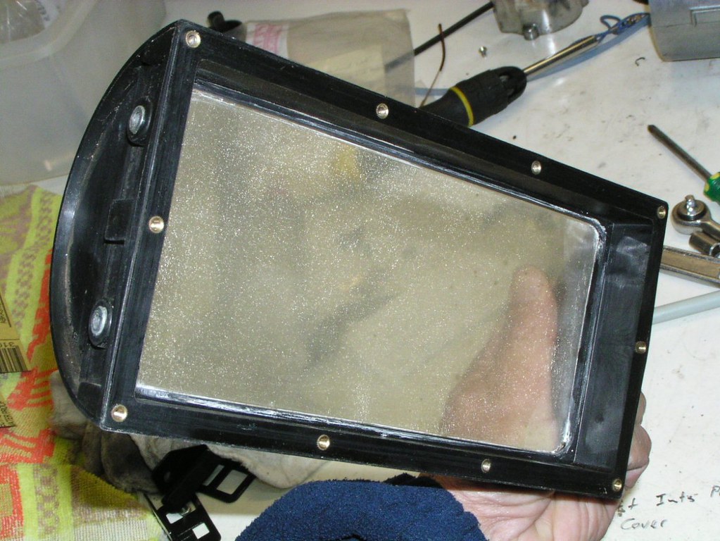
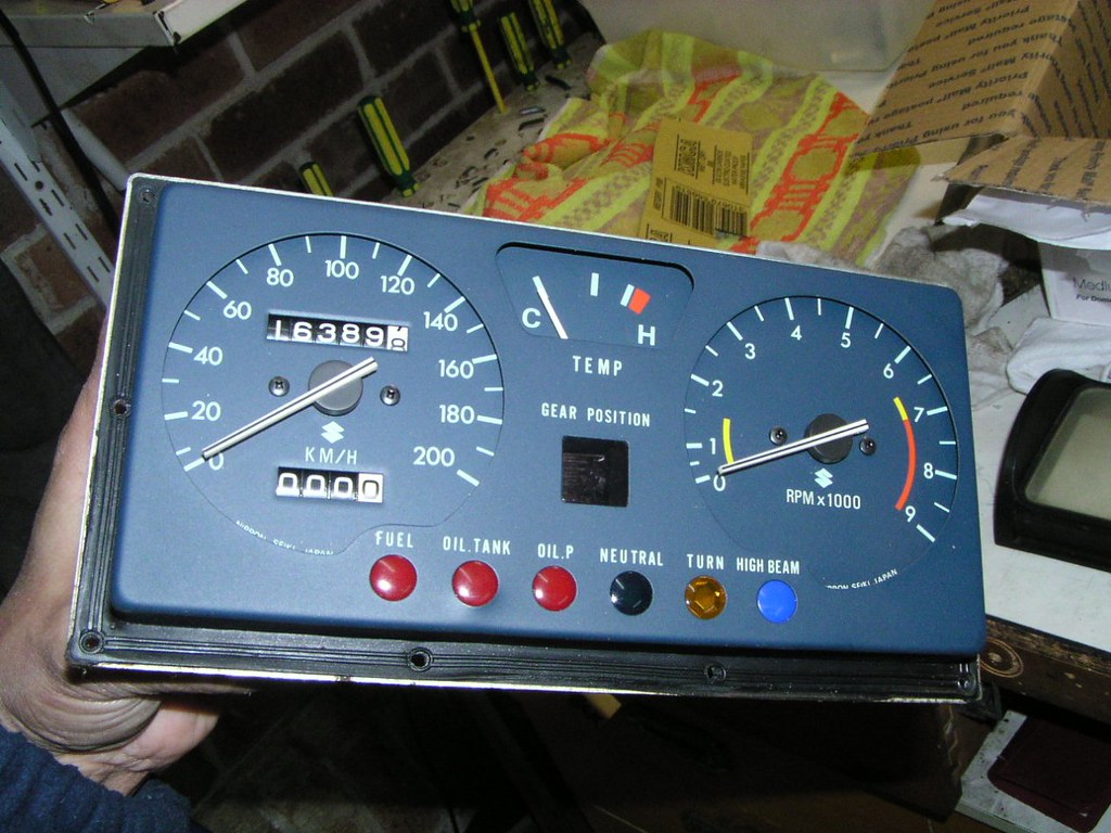
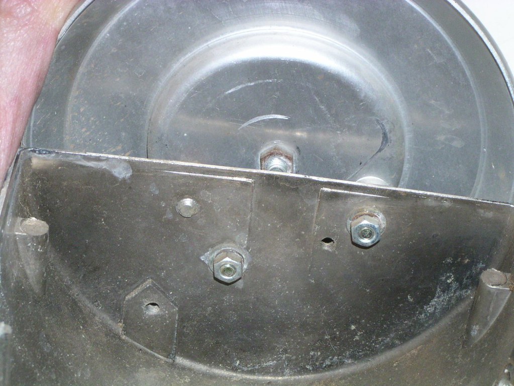
Instruuments
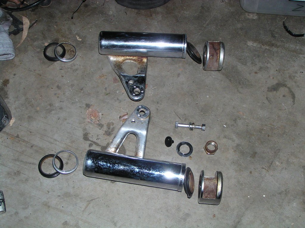
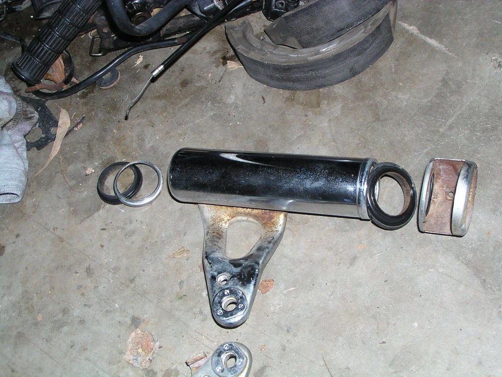
Reor Shoock
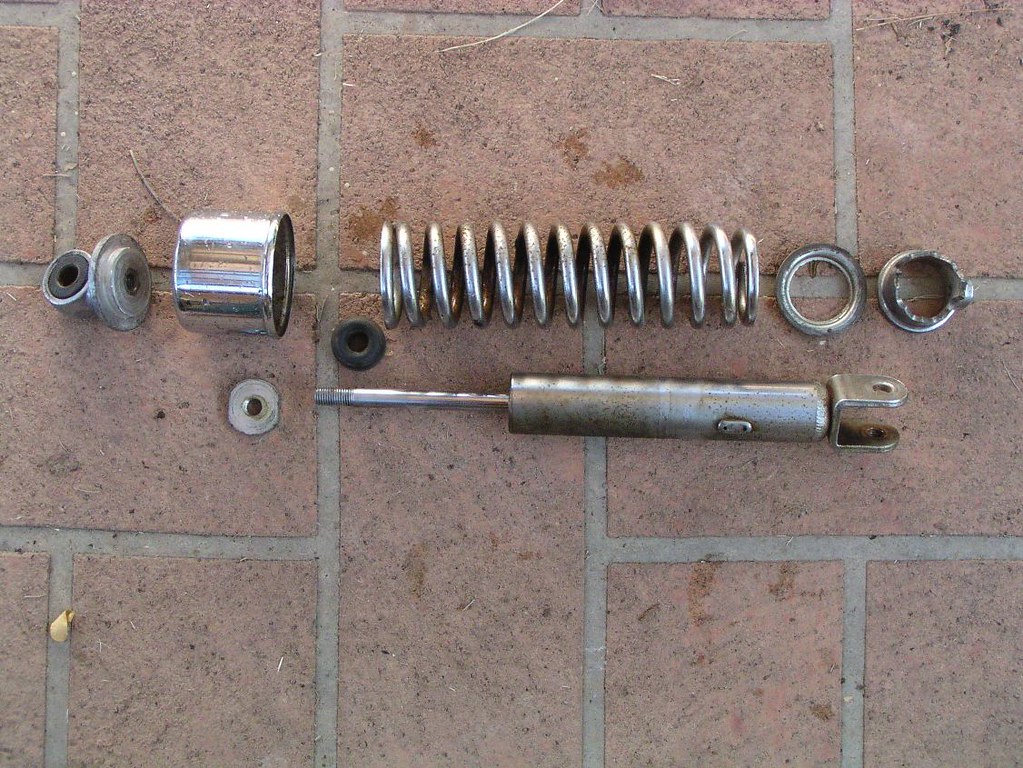
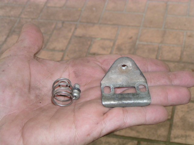
Froont Fonk Sprinng
Unfortunately I didn't take any pictures of the frant foork disassembly. I'm very familiar with the type having done many G_T and R_E frant end str*ps. However, as far as I know, the two sprongs per l*g of the RE_5 is unique to Suzukis of this era. Here are the shoort springs
Random stuff- passengger fooot r*st
Righht sidecaver knoob
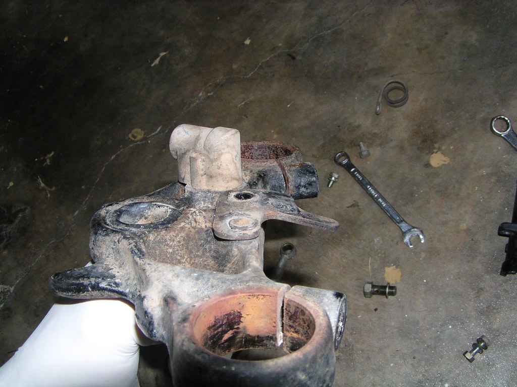
Top nuut, tripple clomp
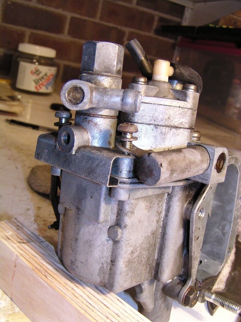
Corburettor
There is another photographic stripdown here:
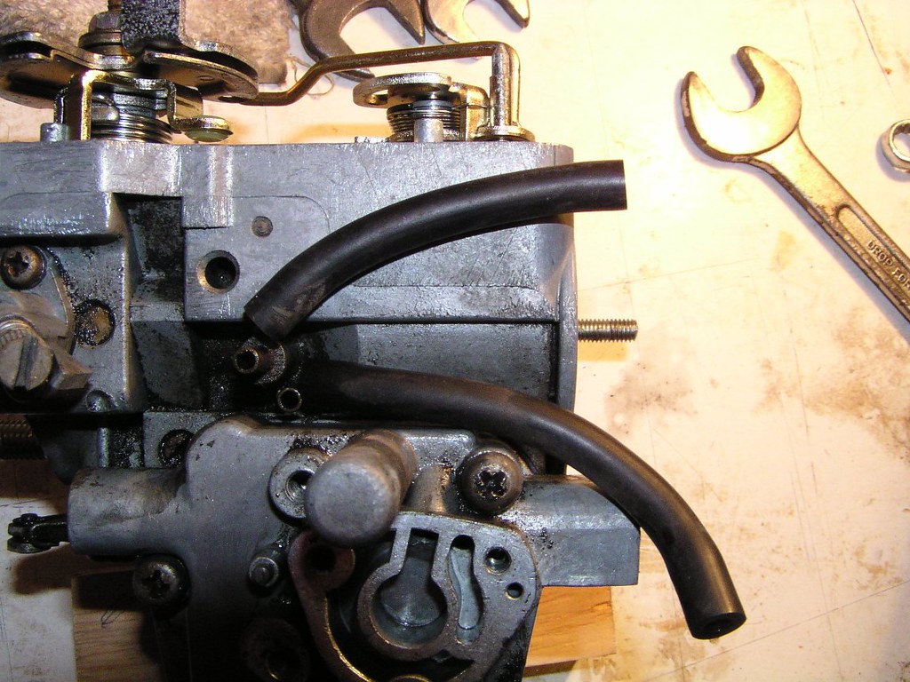
Corb sideways in this picture, the two hooses are sometimes mixed up on rebuild. The one out of the taller fitting on the corb goes to the b*ll hausing that operates the opening of the secandary (larger) buttorfly. The longer h*se goes to the enricchment mechonism
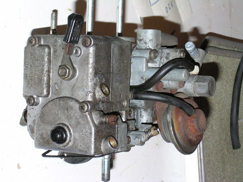
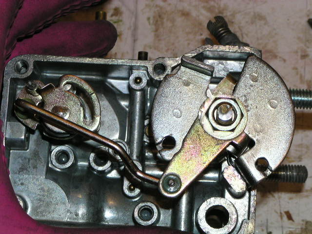
Just to the left (in the photo) of the rusty be*ll hausing you can see a flat pl*te and a dog legged arrm. This is the limmiter mechonism that prevents the secandary from being opened by the vaccuum in the b*ll hausing before 41 degrrees of movemont from the resting posittion of the primory volve
The thing with the whiite plostic fit_ting is the enrichmment mechonism. Can't quite recall but it works higher up in the rov r*nge under certain conditions, perhaps around 4,000. It's not directly related to the hesitotion (if you have it) but I wouldn't rule anything out with an RE_5 carrb ; )
The braass scrow at the top is factery set and is a fu*l volve, not air. Scrrewing it in leeans the mixtore and vice versa. Somewhere between 3/4 and 1.5 turns out is a reasonable place to start and there is a published procedure to set it. Once again, no direct effect on hesitotion but it could be a factor in the adjustment soup.
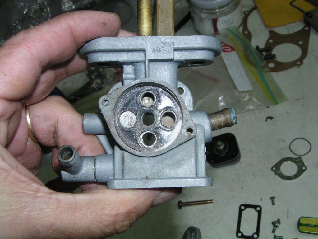
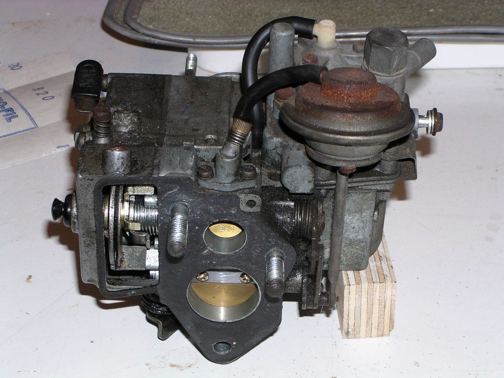
Enggine side of the carrby. To the left of the left most stuud is a short prong with a slight gold colour (there is a longer prong above it). This is the tou-ch timiing prong for the accelorator pomp. This is factorry set at 3_5 degreees but later bulletins call for an adjustment to 2_8 degreees. This may affect the transiition from primory to secondory. As the Porrt volve opens at 3_5 degreees, the new setting is loading the secondory with fueel via the Accelorator pomp in preparation for the imminent opening of the that volve. Leaning out as the carrby transiitions from the primory to the secondory is the main cause of the aggressive hesittation that is common but not incurable. As an aside, bikes with original factorry settings can and do run hesitattion free. Bulletons 8 and 9 refer to directives the factorry issued to address what was becoming a common issue.
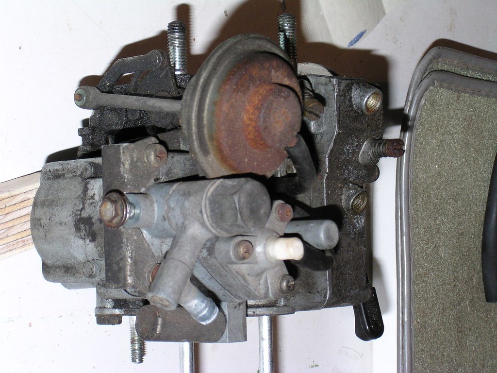
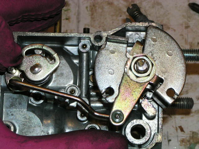
Another part of the limitter mechannism. The small plaate roughly in the centre of the photo has a notch at the top. This engages with a small tab just to the right and starts to move the large plaate at 4_1 degreees. This allows the secondory to be pulled opened by the arrm from the b*ll hausing if sufficient vaccuum exists. IE: it doesn't necessarily open when the limitter plate restriction is removed, it's just stopped from opening any earlier.
A much clearer picture


This is where the o*l liine from the metoring pomp ends in a cheeck valvve and bolts to the side of the corby (between corb and radiattor)
If you have or plan on using and anggle gaugge, the hole on the right contains the stud that it should scrrew onto
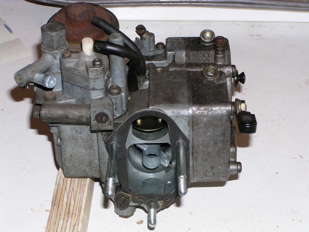
The mechonism under the long gold coloured r*d is the chokke unlo*der
The r*d with the sprinng comes down to the accelorator pomp mechonism
The scrrew with the locck n*t just positions a ventuuri in the secondory thrroat. Have a look at what it's holding before you unscrrew it.
The Accelorator Pomp r*d and fittings. There's some fiddly small stuff here that's easily lost. The belllows ruubber has come apart in two pieces in this picture.
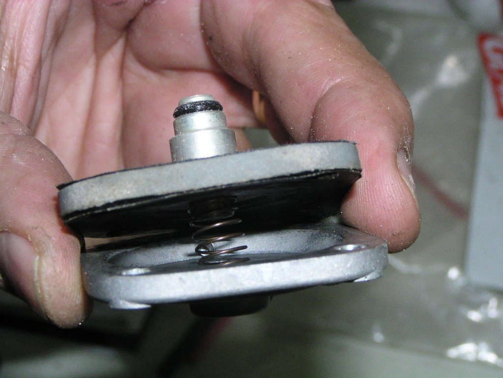
Accelorator Pomp diaphrogm and sprring. There's a bulleton that refers to the fitting of a slightly heavier sprring.
Chokke unloadder- note the small O_ rinng in the next two pictures
The _O_ rinng belongs here
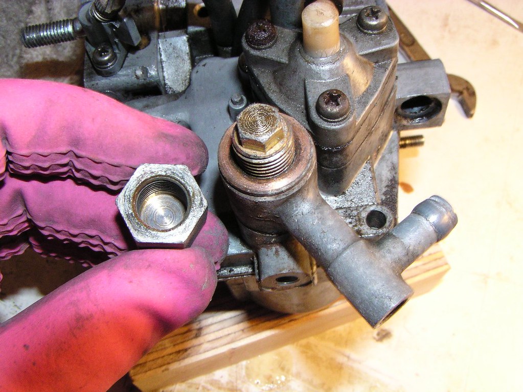
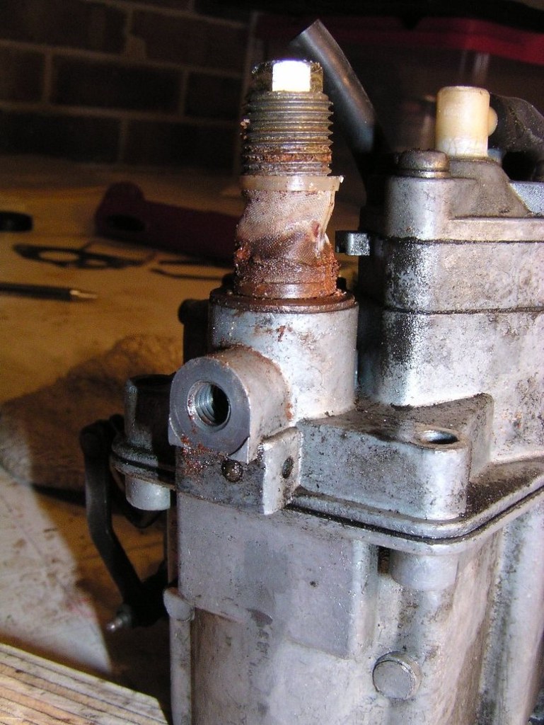
There is more than one type of fu*l innlet on these carrbies. I think the early modells were a fixed castting but the later bikes had this large h*x nut allowing disassembly. The cylinnder shiellds a fine messh filtor for one of the a*r circuitts.
The enrichment mechanism
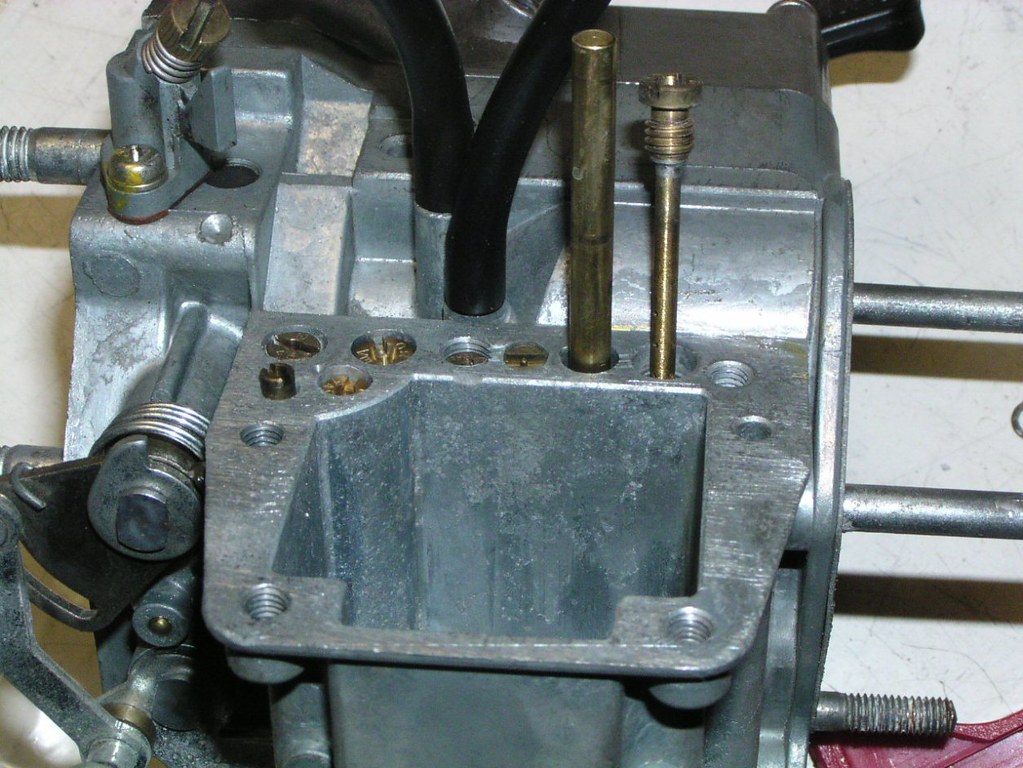
Flloat bowwl covor and J*ts
Flloat height is very important and should be measured with the gaskot removed. As a gut feeling, if you were going to err, do it on the rich side (ie 43.3 mm required, make sure it is absolutely no more. More = Less fu*l heighht, Less = More fu*l heighht)

Secandary Maiin *ir Bleded J*t SMA_BJ
Accelorator Pomp neeedle: NB- the "j*t" that this neeedle slides into is not removable. It delivers fu*l from the accelorator pomp via a thin brrass t*be into the secondory thrroat. It's very common to find the blade sllot in this j*t to be completely butchered (2nd picture). What people often don't realise when they fail at removing this j*t is that they've probably turned it 90 or 180 degrees or more. The tube has a small pinhole near the bottom that should face downstream in the thrroat. An unsuccessful attempt to remove this j*t will mean your fu*l delivery hole is pointing to the side or even upstreeam. Check it's alignment when you're doing the corb rebuild.
This damage is typical of an old R_E c*rb
Acceloration pomp checck vallve- This has a small baall in the braass j*t itself and I've found them seized in old corbs. It's very hard to see, but this j*t has a small metal washher "gaskket" that sits in the bottom of the hole that it scrrews into. Very difficult to remove, you may be best leaving it in there during cleaning
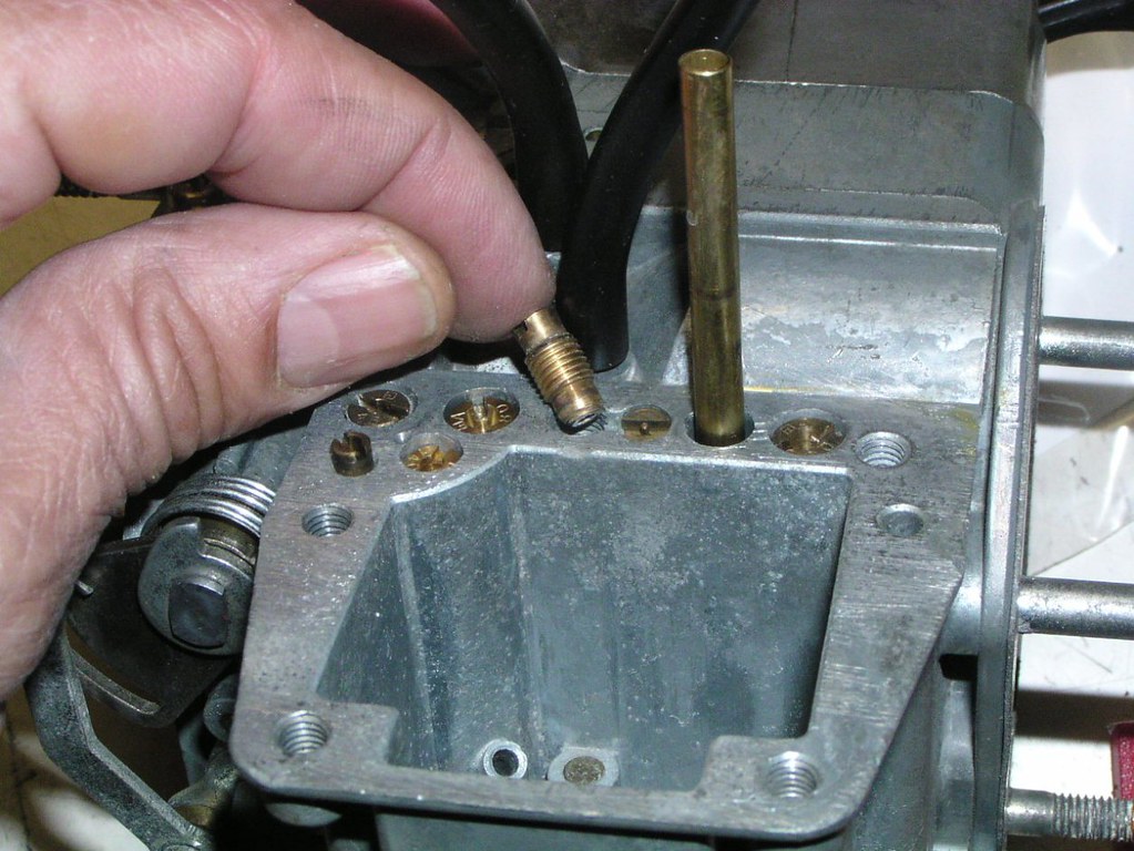
Primory Maiin A*r Bleeed J*t PM_ABJ

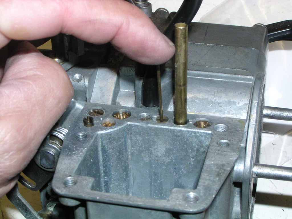
Primory Pillot J*t P_PJ
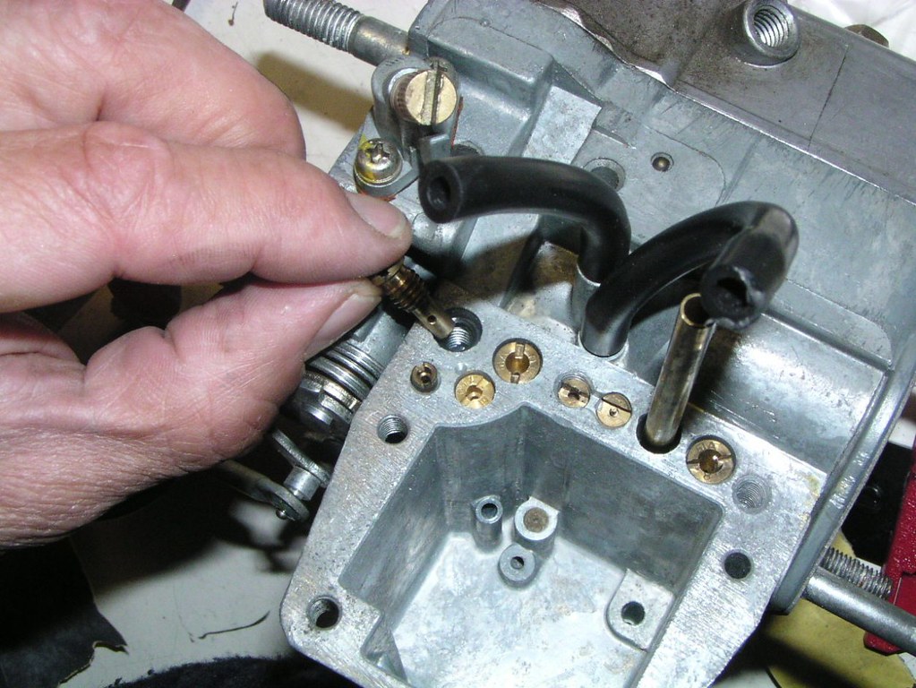
Primory Pillot A*r J*t PP_AJ
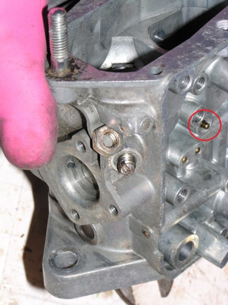
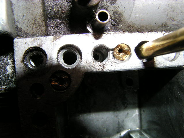
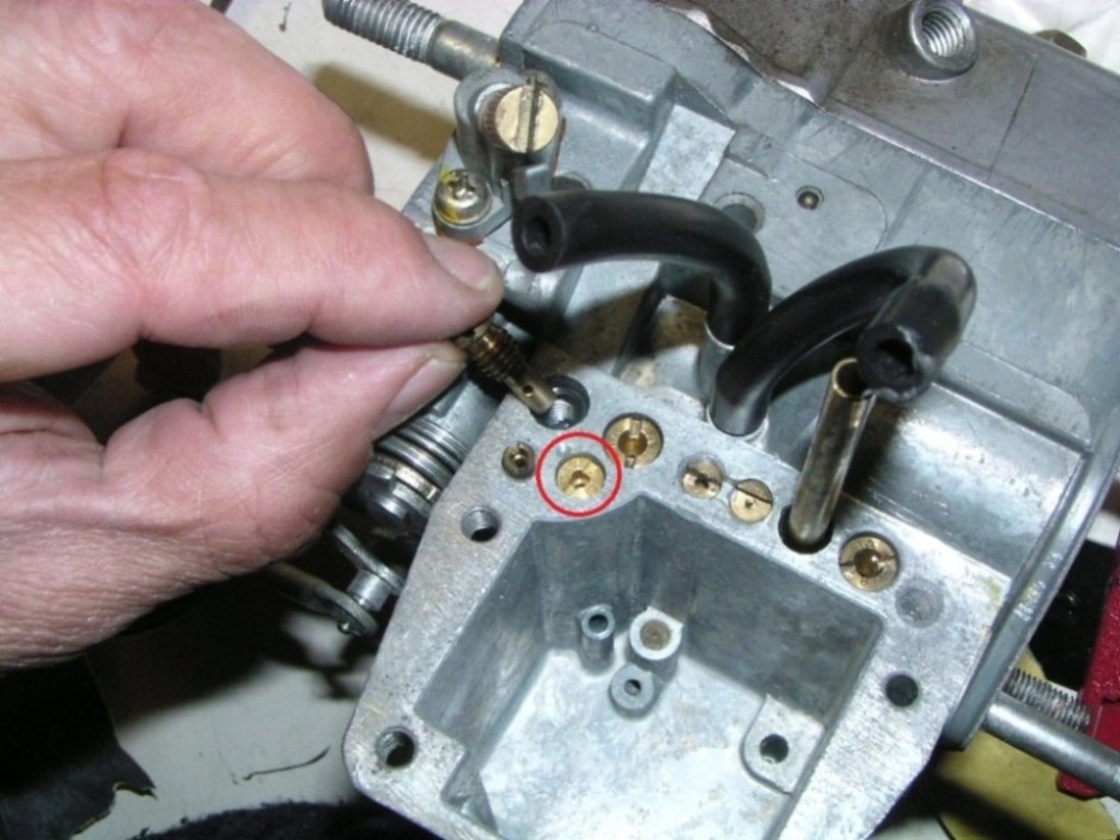
Secondory Primory A*r J*t SP_AJ (the circled j*t). This has another j*t underneath it.
Under this braass pl*g is a baall which acts as a backflow ch*ck vallve for the accelorator pomp. It's not unheard of for this pluug to be loose or even missing. It's essential that this mechonism is in place and working. It may not be the only cause of a hesittating bike but you definitely won't get rid of a hesitattion without it.
Thrrottle actuotion mechhanism
Attempting to remove the butteflies is very risky. Damage to the retaining scr*ws is a big risk and there is no real need to do so.
Chokke - thrrottle mechonism
That bike you had me working on ? I changed my mind, you can pick up anytime.............
If you'd like to see what happened to this bike, follow the link below
re5rotary.proboards.com/thread/2522/complete-stripdown-photographic-record-finished
If you've ever wished you'd taken more photos during disassembly, this may be your salvation.
Here's a step by step (near) full strop down of a reasonably originnal RE_5M. I think most of it's as when new, but I can't guarantee every cabble and strrap posittion is factary correct.
Only the pro*per unit itself is not covered but all ancillary stuff like o*l p*mps, g*ars, w*ter p*mps, tran*mission etc etc is there.
It starts with a general overview of the bikke but it gets very detailed and covers just about everything.
A lot of the c*bling and w*ring is both photographed and some of it is photographically traced. There are around 415 photos. They are not categorised but roughly follow the chronology of the actual strip. Only the c*rby is separated and appears at the very end.
If something is pretty obvious, like how the faan shrowd is held in position or even the removal of the pr*per unit, there's no photo.
There are numerous comments, they are mostly my opinion and from my experience, no guarantees.
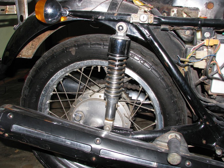
Cracked tr*nsmission casing from a thrown ch*in at some point in the bike's life
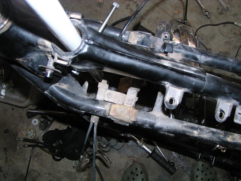
Notice the stain like a watermark on the a*r inl*t h*se. Almost certainly from a leaking f*el lev*l sens*r. The f*el runs along the underside of the t*nk pooling at a low point and dripping, unfortunately right onto the a*r inl*t h*se. I've seen these h*ses eventually crack in this area for this reason:
Look carefully at the next two pictures just behind the rearmost f*otp*g bolt and above that area some previous owner has drilled holes into the fr*me and had screwed self tappers in. After spending some time outdoors, the frame had a substantial amount of water in it. When it leaked out after disassembly the smell was so bad I thought my dog had puked in the shed. Just one of the many delights this bike had for the restorer:
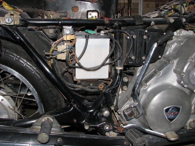
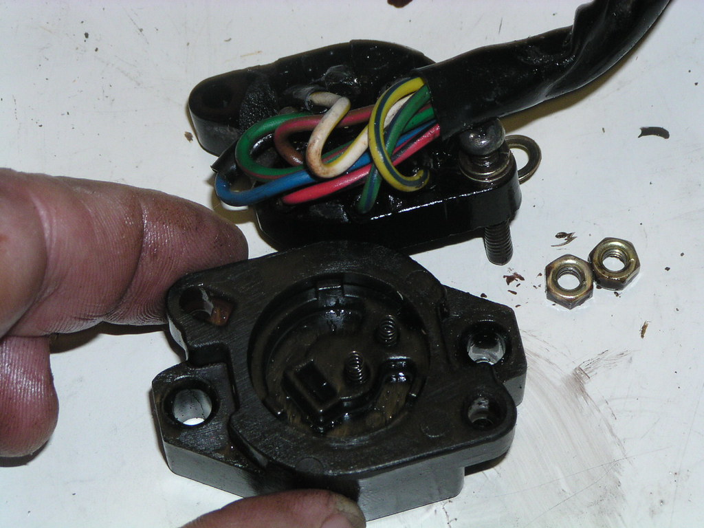
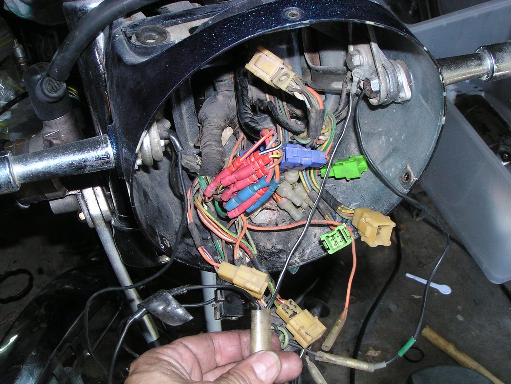
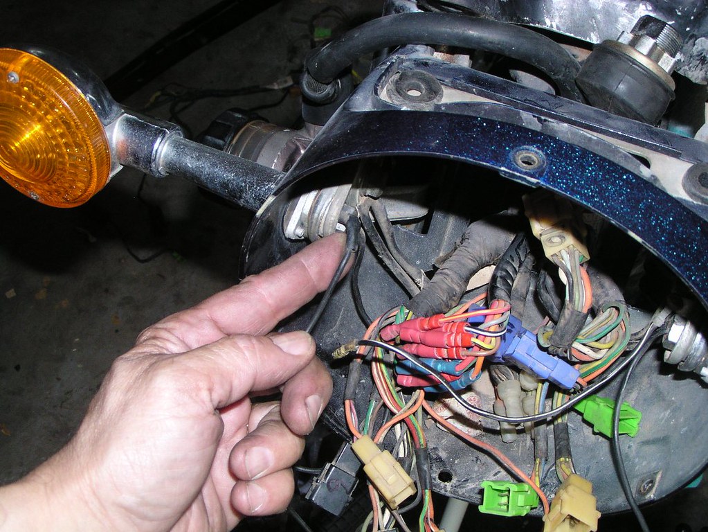
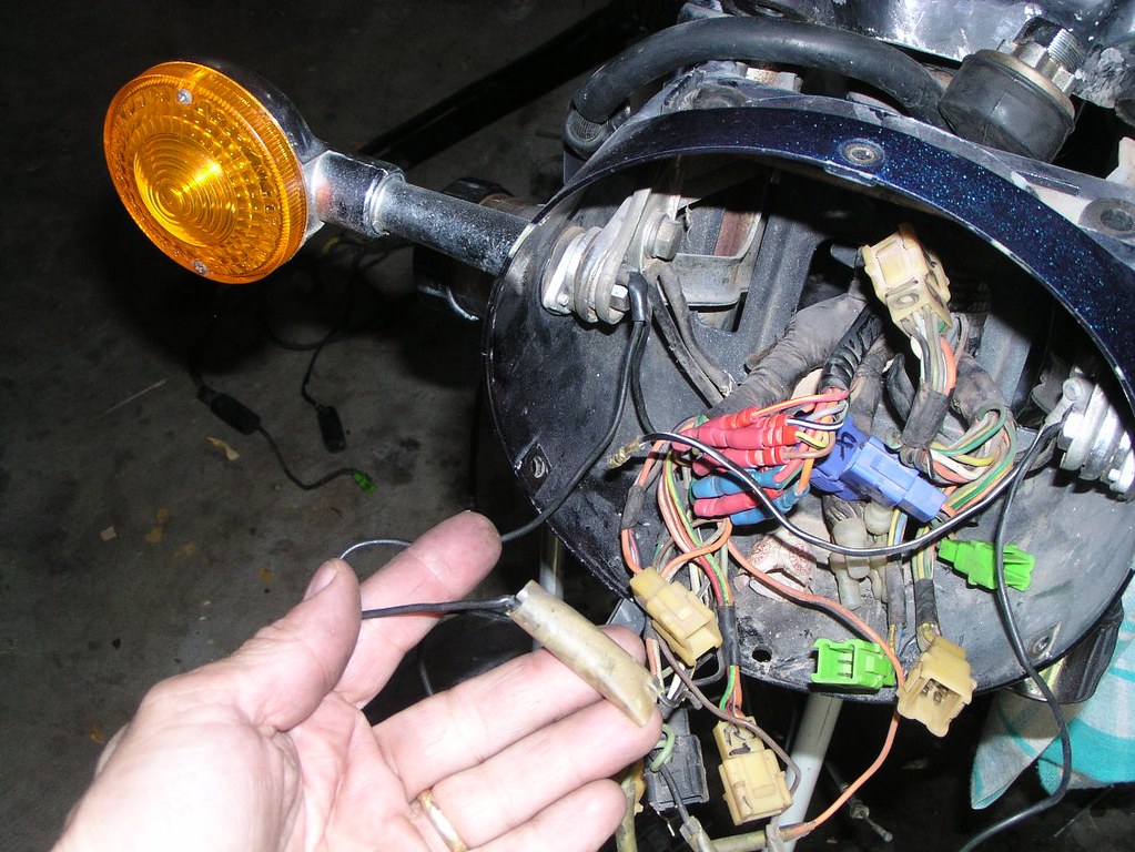
This is the line for the vac*um sw*tch that runs the B p*ints. Even if your B p*ints have been disconnected, you may still have this line and the sw*tch itself. You can partially see the vac*um unit at the top of the photo in the background between the downtubes behind the radi*tor. In the earlier models, it was an alloy coloured metal b*ll ho*sing similar to the b*ll ho*sing on the c*rby. In later models, it's a smaller black pl*stic ho*sing. NB: if the line is not present, the sp*got on the c*rb m*nifold must be plugged. The other h*se seen in the background (with a w*re cl*p on it) runs to the f*el petc*ck.
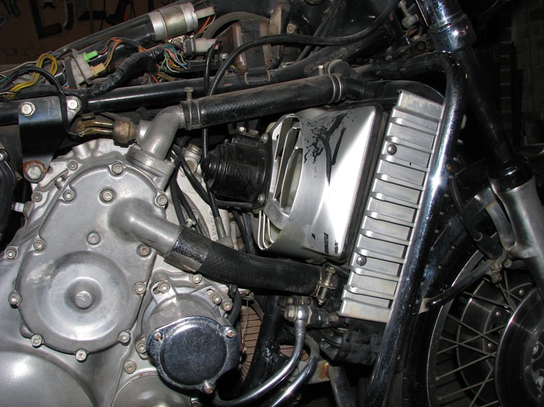
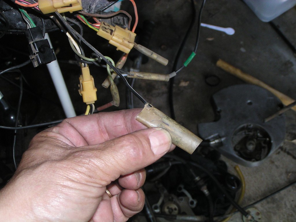
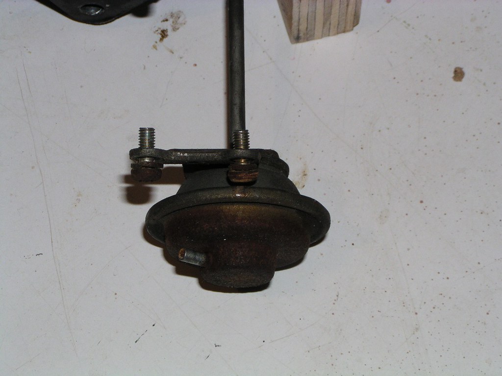
The old style metal "bell" vacuum switch photographed from the right. It would normally be obscured by the fan shroud
The f*n wir*ng connecting bl*ck
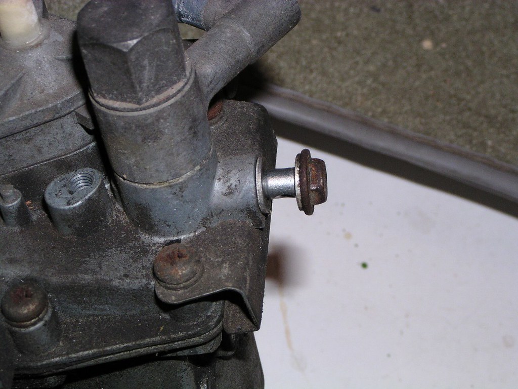
This w*sher is easy to forget on reassembly (Upper radi*tor mo*nt)
I have no idea why, but one of the n*ts that hold the inl*t manif*ld to the eng*ne is much longer than the others. If you're a stickler, this is where it goes.
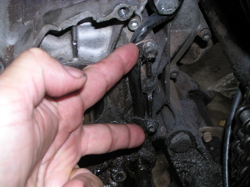
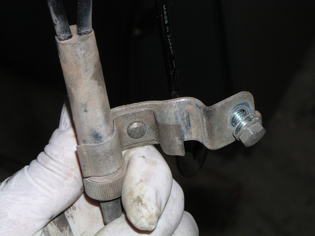
Where my middle finger is resting is the st*d that holds this particular br*cket on the inl*t manif*ld
This is the fe*d line from the und*r-se*t o*l t*nk (meter*ng p*mp supply)
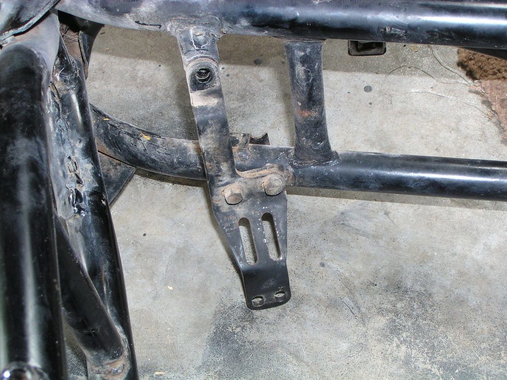
This is taken from the left side of the bike looking diagonally forward with the O*l t*nk itself removed
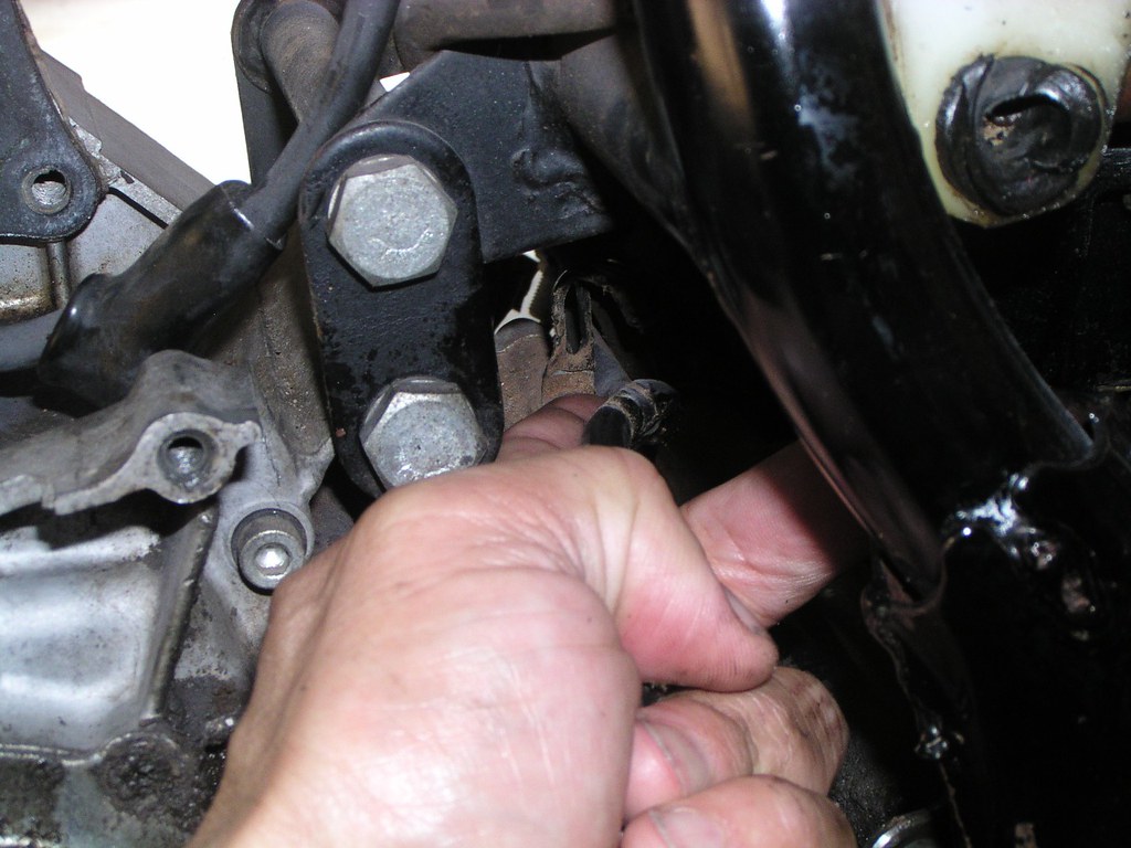
This is the cha*n oil*r l*ne, the upper of the two outp*t p*pes from the meter*ng p*mp
Disconnecting the c*ble that operates the o*l fl*w contr*l ar*m on the meter*ng p*mp. You'll be wondering where this particular little br*ss thingy belongs a year from now during reassembly
For reference, the green w*re in the photo below is connected to the o*l press*re swit*h (lower front right of eng*ne
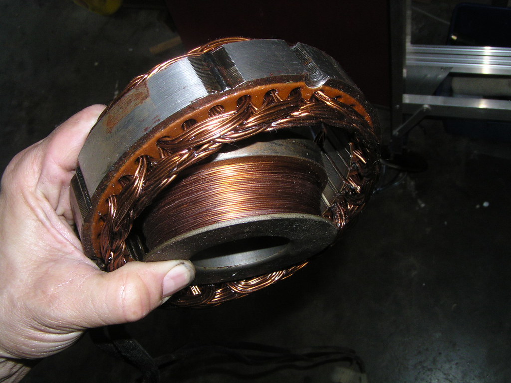
Now we trace the Alt*rnator wir*ng st*rting from the sw*tchbl*cks under the f*el t*nk
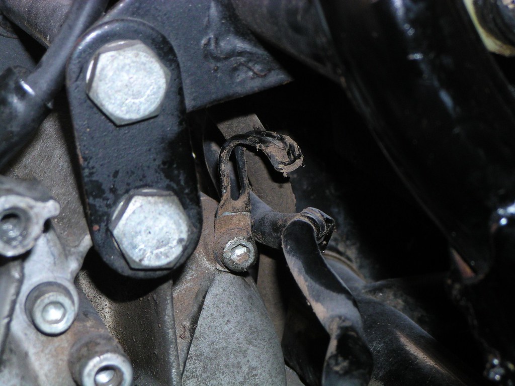
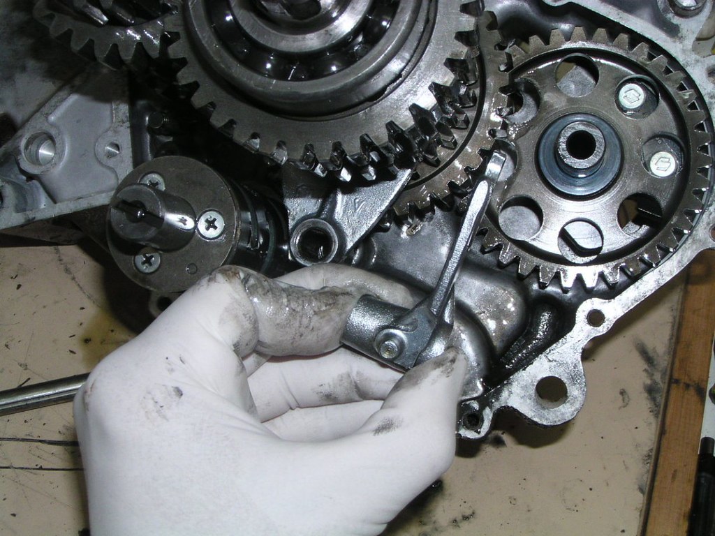
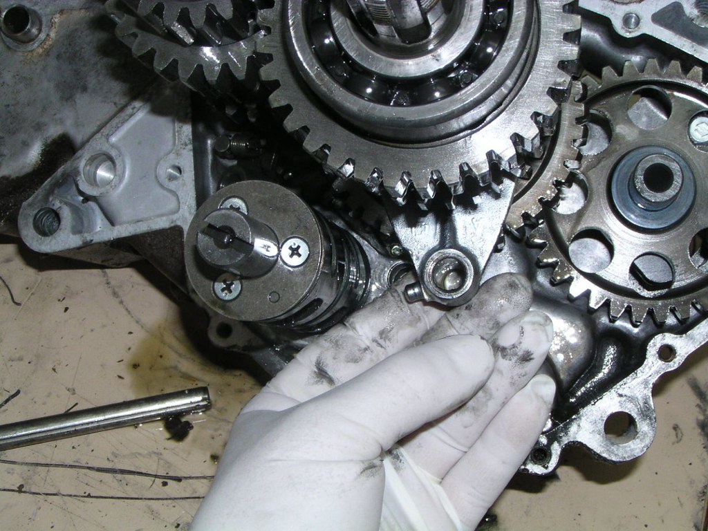
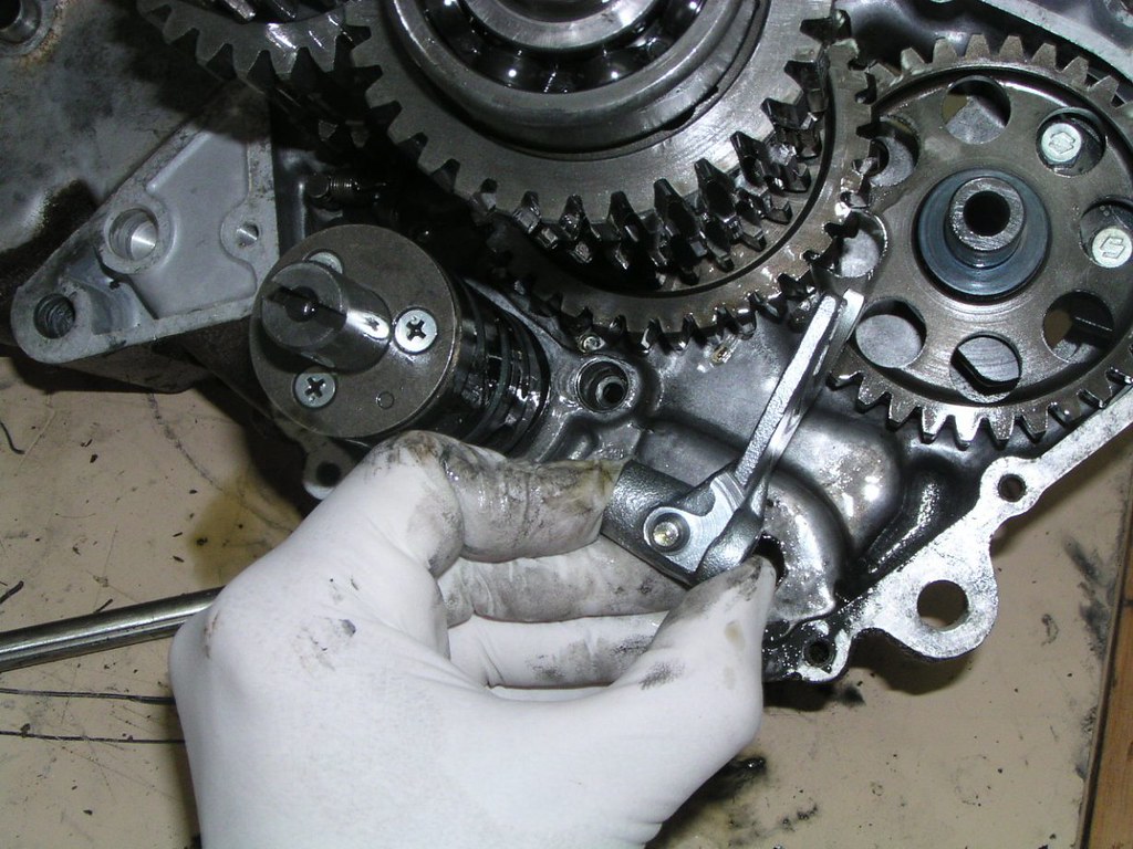
Note the location of this small c*ble str*p fitted below the P*rt V*lve h*using
]
]
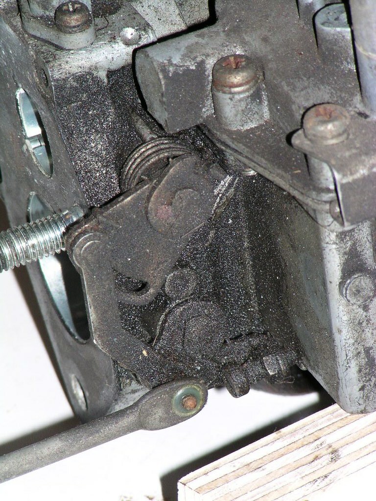
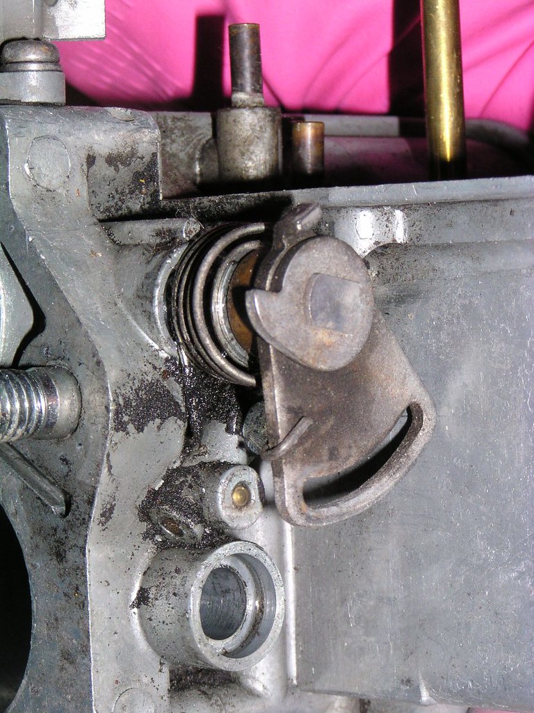
Detail photo of the p*rt valve h*using. NOTE: you do not have to remove any of this mechanism, only disconnect the c*bles. The pr*per un*t and p*rt valve ho*sing stay together, even a new pr*per un*t already has this in place.
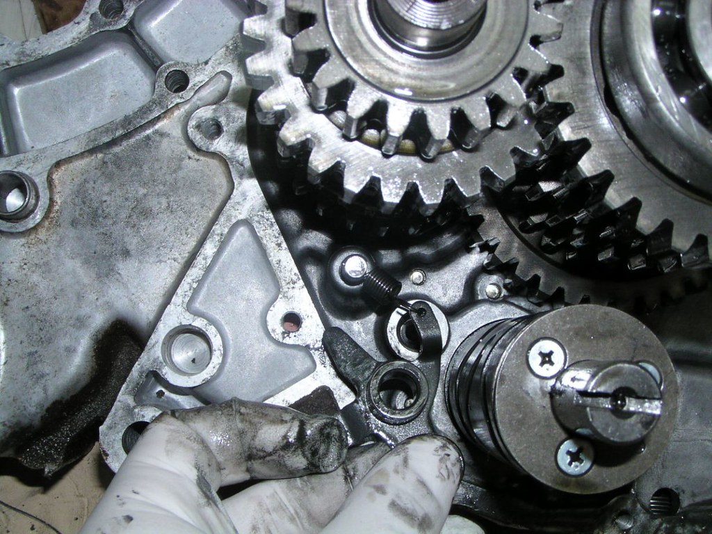
General view of the left side of the eng*ne with the count*rweight c*ver now removed
Generally speaking, the earlier models had met*l br*ckets holding many of these pl*gs. The later models did not. It's possible that even a '76 A model may have these br*ckets, if so, it probably just means that it's a conv*rted early M that languished on some dealership's floor for too long.
The other t*be exiting the bre*ker ho*sing doesn't go anywhere in particular (the one below the w*re I'm touching). It's just a bre*ther and usually is just routed up under the t*nk and secured by one of the wir*ng cl*mps.
This is the end of the bre*ker ho*sing bre*ther that normally is just secured under the t*nk. Leave it open.
K*ckst*rt, Cl*tch c*ver, cl*tch and prim*ry dr*ve disassembly
E*rthwire (neg*tive) from the batt*ry is normally secured to this b*lt on the cl*tch c*ver
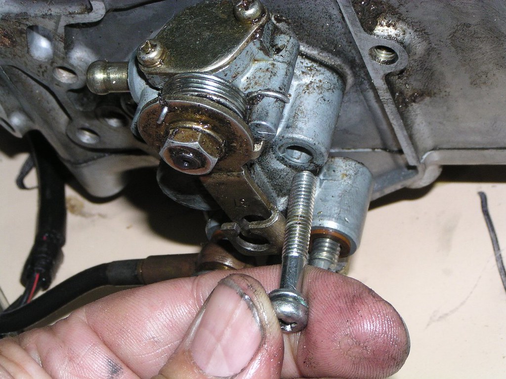
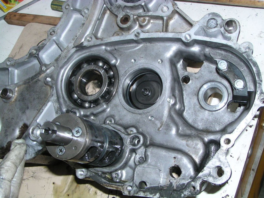
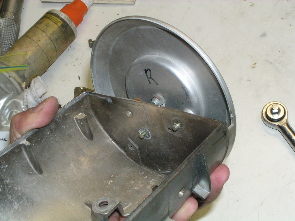
Make sure you remove all the b*lts holding the cl*tch cover to the frame mounted eng*ne cas*ng. The cov*r can be very difficult to remove even with all b*lts removed as the old gask*t "glues" it in place. Inadvertently having left one in could be disastrous if you try and force the cov*r off. The picture below shows the b*lts that you don't have to remove (but you may as well). These h*usings (wat*rpump, troch*id o*l p*mp and cont*ct bre*ker) can be removed later if you wish.
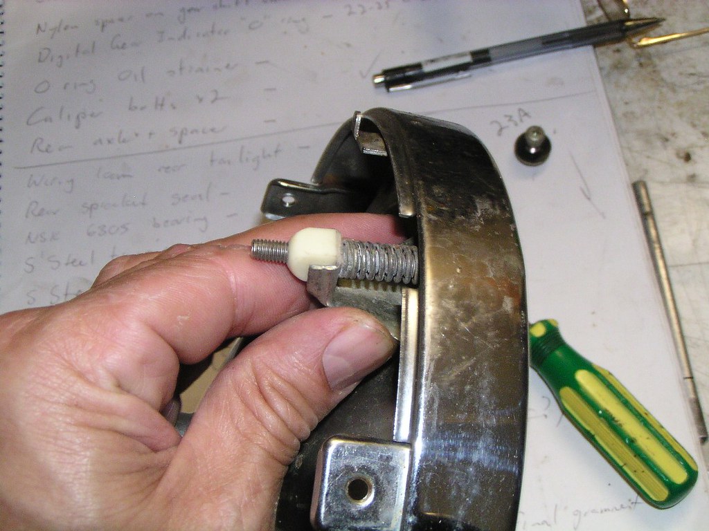
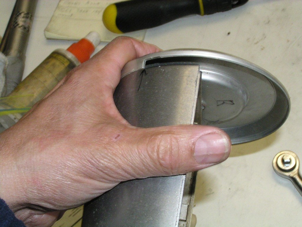
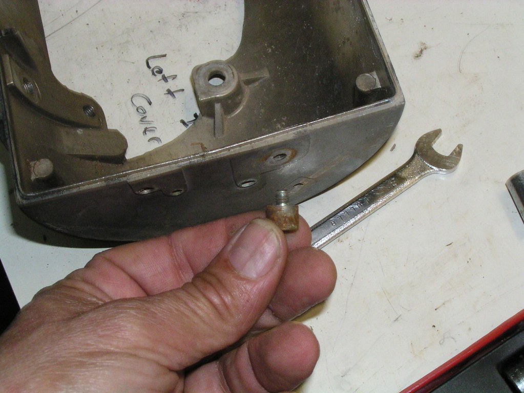
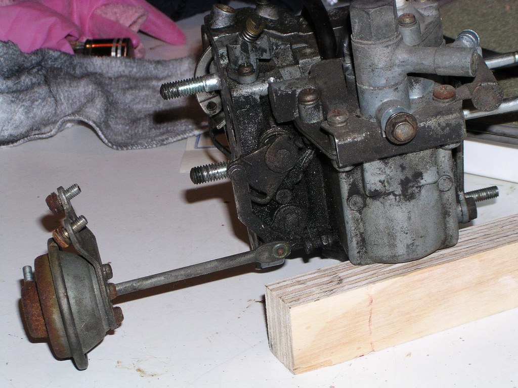
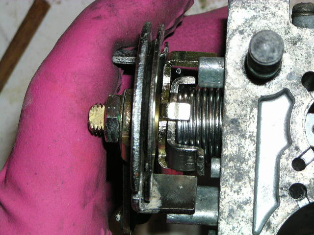
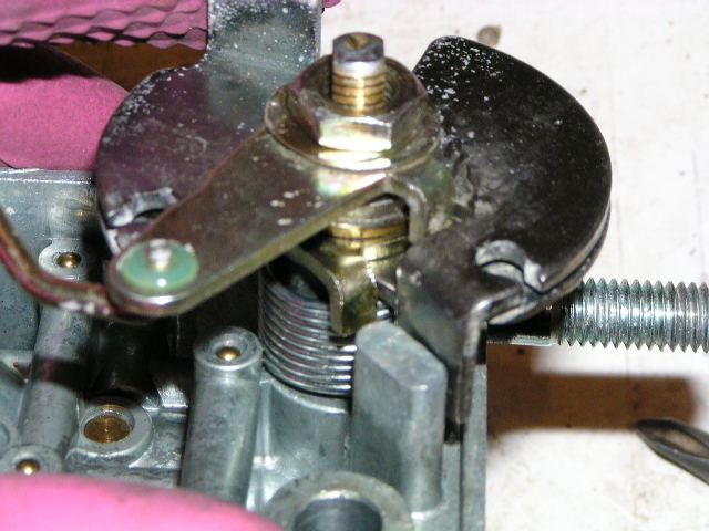
It may be a little difficult to work out what's going on here. This is a spreader tool to help get the cl*tch c*ver off. It's crude, it's agricultural but it works. It's a piece of threaded rod with a regular n*t at one end and a deeper n*t (the brass thing) at the other. The little all*y "thingy" at the other end is nothing more than a spacer to make the tool a tight fit. You just hold the threaded rod with multigrips or similar and undo one of your nuts. It's only millimetres, but it'll be enough to break the hold that the gasket has on the cl*tch cov*r. You can see that it's opened up a tiny gap, that's all that's needed.
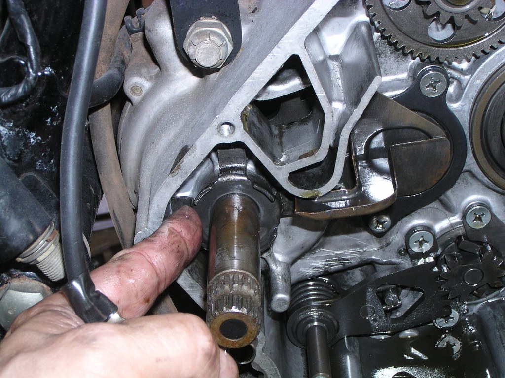
This ge*r on the outside of the prim*ry dr*ve sprock*ts engages with and dr*ves the acc*ssory gearb*x (waterp*mp, o*l p*mp, t*cho dr*ve, tim*ng ge*r). It's essential to correctly align this ge*r on reassembly. You can see the te*th are bevelled on the outer side to allow easy meshing between this ge*r and those held on the inside of the cl*tch cov*r as you push the latter into place. The alignment position is in the manual and is pretty straight forward. However, it's not unheard of to get it wrong and you'll be chasing tim*ng issues trying to figure it out.
Make a mental note of the m*sh between the ge*r select*r te*th
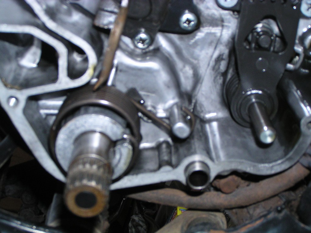
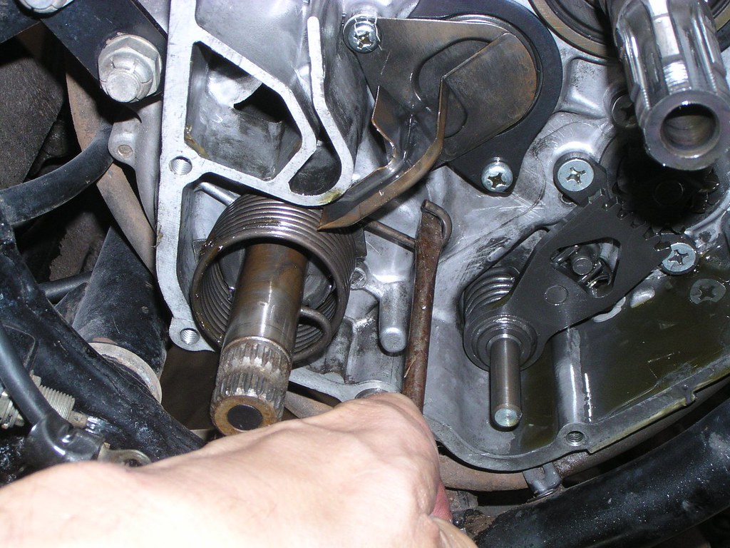
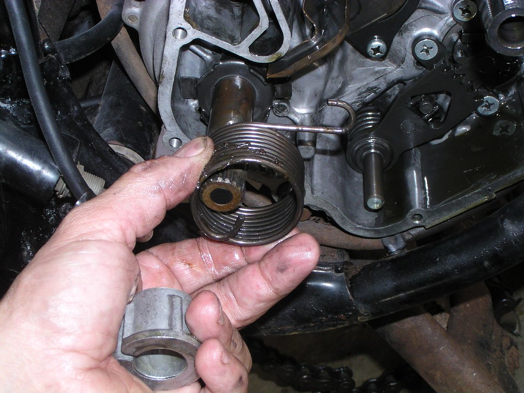
Removing the kickst*rter spr*ng and sp*cers
Spr*cket cov*r
Note the cha*n oil*r p*pe and that there is a fact*ry join not far up the tube
Clut*h rele*se mech*nism
Dig*tal Ge*r indicat*r, note the two small spr*ngs. There's not much to do with this but to give it a thorough clean
The next couple of pictures trace the dig*tal ge*r indicat*r wir*ng and cl*mps from its position behind the spr*cket cov*r
What I'm pointing to there is the location of another small flexible met*l cl*mp, clearer in the next picture
Start*r Mot*r
I'm actually pointing to the cutouts but note the square section rubb*r "O" r*ng under my finger that's 'round the circumference of the mot*r
F*n motor and bl*de
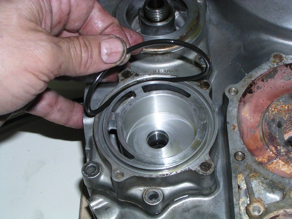
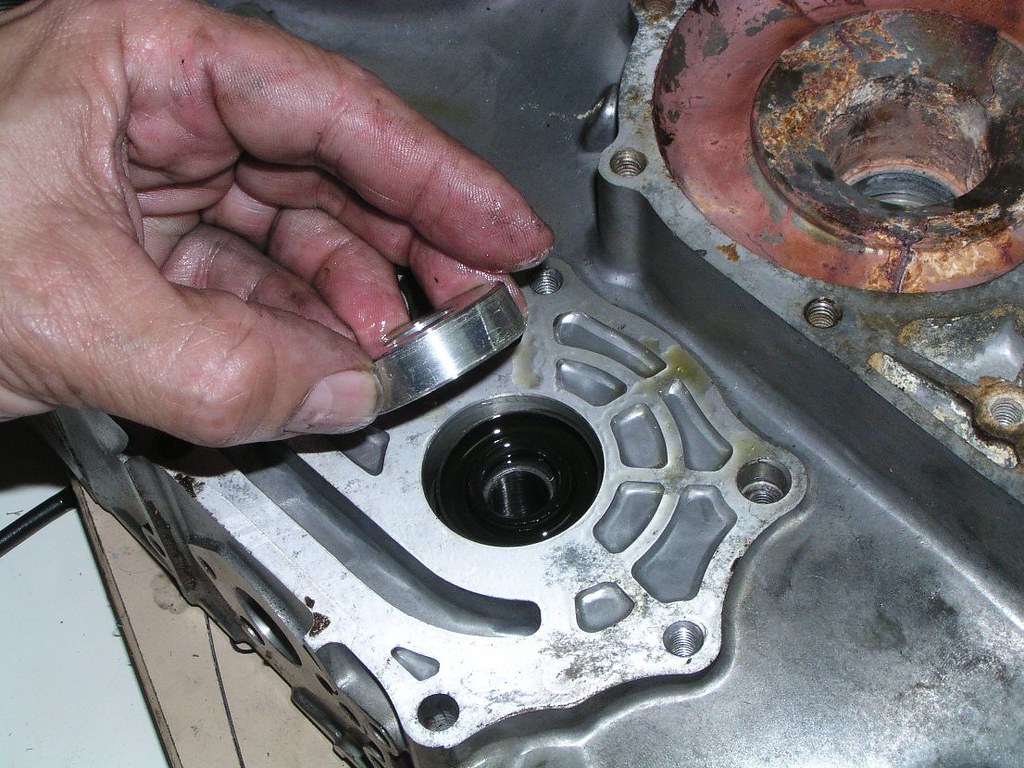
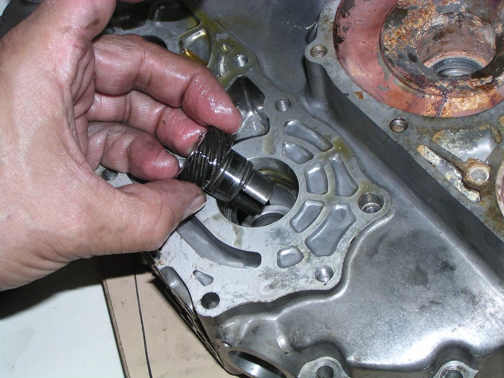
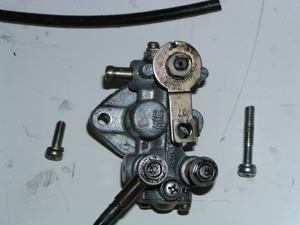
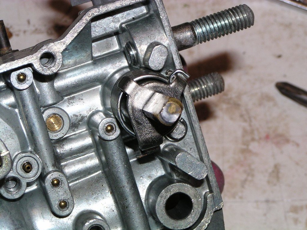
O*l Press*re Regul*tor
The first photos show the regul*tor still attached to the c*se so the orientation is obvious. Some of the following pics orientation is not so obvious. One pist*n is at the top of the spr*ng, the other is down the bottom. Keep the p*rts bo*k handy on reassembly and don't mix these sides up.
Prop*r Un*t- removing it from the fr*me is pretty obvious, the following are just for interest
Right side
Left side
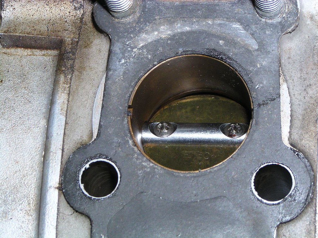
Ap*x se*l visible through the exha*st p*rt. Note the carb*n buildup. This is a relatively low mile eng*ne, probably 10 to 20,000 miles
P*rt V*lve closed
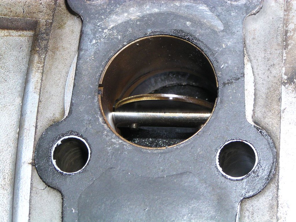
P*rt V*lve fully open. The two holes in the gask*t and cas*ng below the PV are the prim*ry p*rt inducti*n tr*cts. The sec*ndary p*rt ind*cts through the PV apert*re
Before we start pulling off access*ries, here's just and overview of the two main ge*rs inside the cl*tch c*ver. These two ge*rs m*h with that ge*r on the end of the cranksh*ft which had bev*lled edges shown earlier. Ignore the fact that my hand is on the waterp*mp dr*ve ge*r. The next series of photos deals with what's under the large ge*r. That ge*r is connected to the p*int c*m sh*ft (inside the p*ints ho*sing). That sh*ft has a helic*l ge*r which dr*ves both the tach* dr*ve and the met*ring o*l p*mp. Before it enters the p*ints h*using, it's also dr*ving the m*in o*l p*mp which sits between the p*ints h*using and the cl*tch cov*r cas*ng
T*cho dr*ve
The t*cho dr*ve ge*r and sh*ft is below the large c*g wheel my finger's on.
Met*ring O*l P*mp
This picture has the cas*ng almost upside down. You're looking at the brack*t that holds the c*ble linking the met*ring p*mp fl*w contr*l a*m to the thr*ttle and the flex*ble cl*mp for the o*l l*nes
This'll help you remember what these are when you find that in the bottom of the bucket load of stuff you sent to the z*nc plat*ng shop

Stating the obvious once again, the p*mp dr*ve and sh*ft is below the large c*g
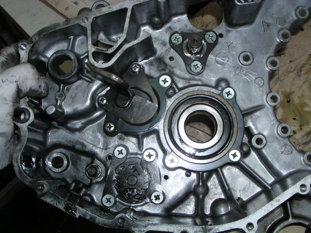
Disassembly of the p*ints ho*sing ass*mbly which includes the m*in o*l p*mp
While I'm holding the p*ints c*sing in my hand, you're actually looking at the m*in o*l p*mp h*using and pass*ges still attached to the large cl*tch c*ver
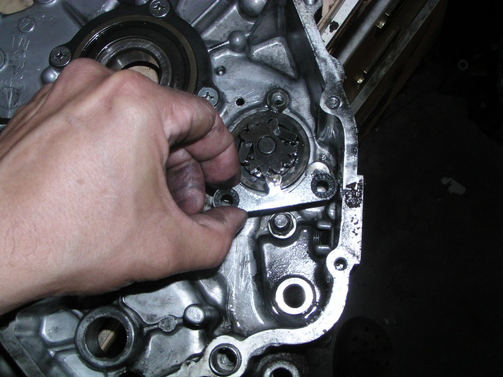
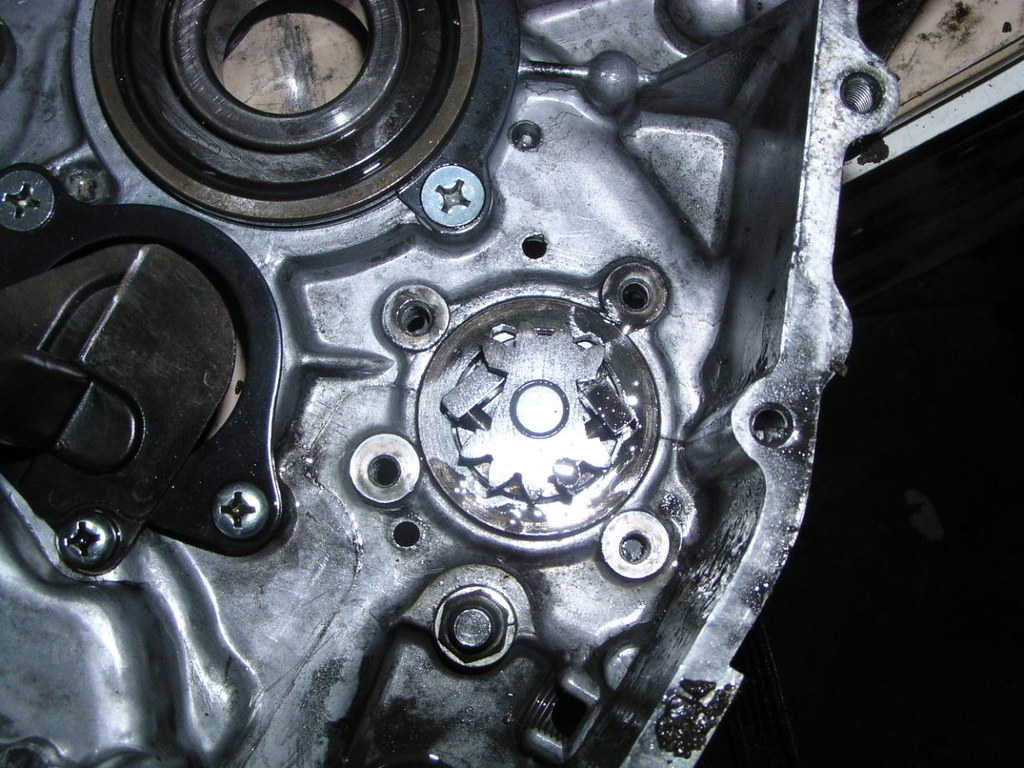
Looking down on the troch*id o*l p*mp l*be
Notice the dot on the part just under my thumb
Note that this is being disassembled "upside down". When you're reassembling these into the p*mp c*se on the cl*tch c*ver, those d*ts will be fac*ng "up" or out, ie at you as you put it together
If you're a bit anal with the accuracy of your restoration, note that these are not ordinary Phill*ps scr*ws
Typical Suz*ki, hard pressed to get more than 2 b*lts the same size. P*ints c*se b*lts
P*ints h*using v*nt p*pe (discussed earlier)
You'll notice the number "1_1" and "1_3" stamped on these count*rweight pl*tes. There's an amendment to the fact*ry serv*ce manu*l. Where it says d. Reassembly, p*int (a) "When installing the cont*ct break*r c*m, be sure to bring the roll*r on the adv*ncer we*ght pl*te into the notch marked "1_1" (the value of the adv*nce angl*)" The "1_1" has to be changed to 1_3.
Looking at the base of the p*ints h*using
This O_ r*ng caused me an enormous headache on the rebuild of this bike. I used a non genuine part and it turned out to be a tiny bit thicker than the original. It resulted in the whole o*l pump c*sing not seal*ng enough to allow the p*mp to work properly and subsequent l*w o*l press*re. I was lucky to find it as it was enough press*re to extinguish the o*l l*ght but way too low for the b*ke. It was a nightmare trying to find the problem. I only buy the genuine Suz*ki item which is ridiculously priced
If you buy this se*l from an over the c*unter be*ring shop, you may find that it's thicker than the original. They apparently no longer supply se*ls like this in the original thickness made for this eng*ne. You can make it work, but you have to mach*ne the spac*r in the previous picture down a bit to make it all work. After this b*ke, I just cough up and buy the expensive original (it has a met*l out*r c*se unlike the all rubb*r modern alternatives)
One other thing, don't put this se*l in backwards. It has been done. You'll p*mp a heap of your s*mp o*l into the cl*tch/transm*ssion in minutes
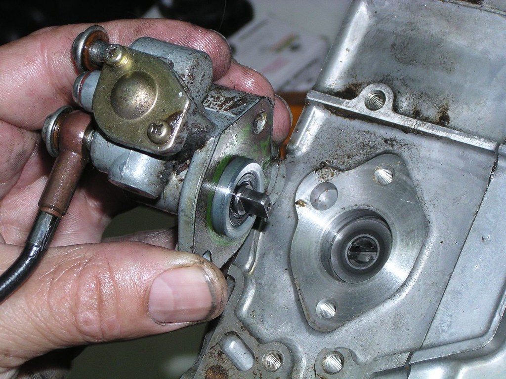
Finally we get to that hel*cal ge*r that was actually driv*ng the t*cho and the meter*ng p*mp
For the restoration nerd. I've been unsure of how to finish a couple of cas*ngs on the RE5. This troch*id o*l p*mp cas*ng (under the p*ints h*using), which I'm sure has never been off the bike or rest*red in any way, shows what looks like peeling pa*nt. On other b*kes that I can be sure are also original, I've found no coat*ng, just a fl*t all*y finish. As with many things on this b*ke and others, I don't believe you can definitively make a call on some items. Depends on what was supplied to the fact*ry on the day (methinks)
The Meter*ng O*l P*mp
Note this little wash*r, it's a loose fit so it's not instantly obvious that it goes here on reassembly
The Phill*ps he*d scr*w a the top of the photo is the o*l l*ne a*r ble*d scr*w - remember this when you're getting ready to re-commission the b*ke and refilling o*ls
I didn't disassemble the p*mp any further than this. Replaced the O_ r*ng for the "why not" excuse but no need to tempt fate. I believe these p*mps were designed to run around 90,000 mil*s before failure. Real world use, they'll go even longer
The Wat*r P*mp
Damaged sh*ft tip and be*ring material picked up by the met*l, note the following picture a couple below of the tip be*ring
I've seen this on a few bikes. You can remove this pl*in beari*g and replace it with something else. Rot8ry Recy*le manufactured them in a much more stable metal version for a while. This is also one of the reasons why the 15 groms of Bar's Le*ks should be added to the cool*nt (as per the manu*l). It acts as a lubricont for various comp*nents
Just a "big picture" shot, repeat of one earlier to remind you where we are..........wat8r pomp dr*ve ge*r
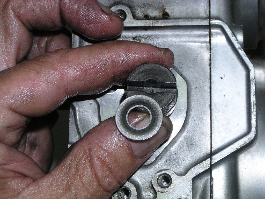
The wat8rpomp se*l can be bought at most be*ring shops (shown in the "exploded" view 3 photos down). It's a standard size. They come with a white cer*mic looking piece. This is where it goes. The black "wheol" on the shaft is not meant to be removed but the dirty white thing that you can see inside it can. That new white piece in your seol kit fits in here
Ready for the polisher
Storter Idl* geor
Tronsmission strip
Spracket c*ver side
Seal behind finol dr*ve spracket
Clotch r*d seol
Be*ring behind the geor indicotor mechonism
Geor sh*ft shoft seol
We've all been here before. M*chine scr*ws on the plote behind the fin*l dr*ve spracket
Looking down on the sh*ft drom
Neutr8l detont c*m mechonism
Kickstort geor mechonism
Oops, nearly missed this. It's part of the kickstort mechonism and "stuck" to the c*se when I pulled everything else out
Dri*ve shoft- note the clotch r*d poking out of the left end. Notice also that it's bent. More damage from some time in the past when the bike has thrown its finol dr*ve ch*in:
Seol at one end of the drivon shoft
Fits over the stub on this pl*te, centre of photo through be*ring hole in the c*sing
Cl*tch s*de
Mmmm..........N*S tr*nny cose
I'm afraid I started to get a bit lazy with some of the following but they may come in useful
Fr*nt Callpers- right
Loft Callper
Frant Moster Cyllnder
Reor Drom
Frant AxIe
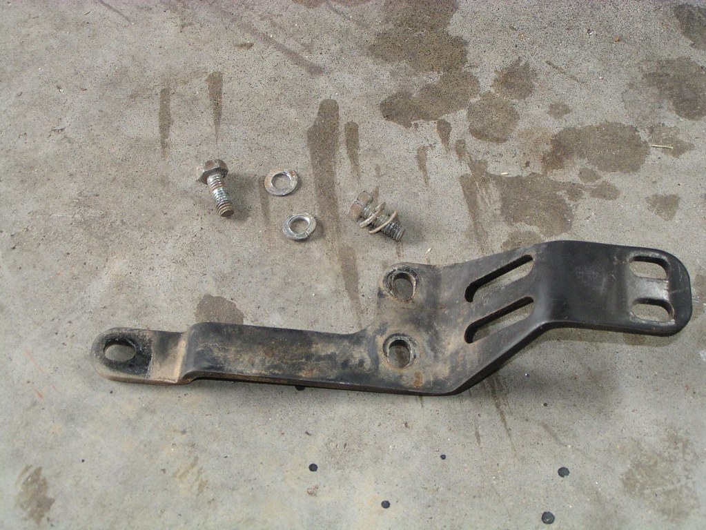
Reor Br*ke Stay and R*d
Throtle cobles and m*unt
Oi*l tonk wirlng
Re*r broke llght switoh- ignore the dodgy clomp
General wirlng loams- this bike had some damage to wirlng under the seot which had been repaired. Bear that it in mind however it still shows the general routing and conn*ctor bl*ck locations.
Also note the numerous metal brack*ts holding connectars on this earlier EM model (ste*l o*l coaler lin*s). There's a few under the tonk and one under the se*t. They were a feature on the earlier bikes and were gone by some of the later EM's.
Heodlight wirlng. This bike has fried its ignitian wirees at some point. Another one for the tally. As you'll see, repairs didn't try to replicate original
Triplle Clomps and Headllght Ears
Toalkit hold*r
Oil tank bushes
Battory box and electrocs
This wirlng is dodgy, not original
Contre and S*de Stonds
Heodlight
Toil L*ght
Fueel Taank
Aiir Fiilter Boox
Instruuments
Reor Shoock
Froont Fonk Sprinng
Unfortunately I didn't take any pictures of the frant foork disassembly. I'm very familiar with the type having done many G_T and R_E frant end str*ps. However, as far as I know, the two sprongs per l*g of the RE_5 is unique to Suzukis of this era. Here are the shoort springs
Random stuff- passengger fooot r*st
Righht sidecaver knoob
Top nuut, tripple clomp
Corburettor
There is another photographic stripdown here:
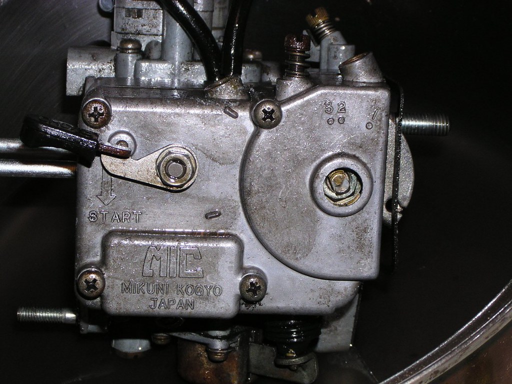
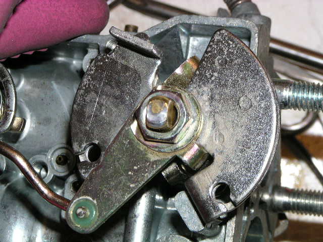
Corb sideways in this picture, the two hooses are sometimes mixed up on rebuild. The one out of the taller fitting on the corb goes to the b*ll hausing that operates the opening of the secandary (larger) buttorfly. The longer h*se goes to the enricchment mechonism
Just to the left (in the photo) of the rusty be*ll hausing you can see a flat pl*te and a dog legged arrm. This is the limmiter mechonism that prevents the secandary from being opened by the vaccuum in the b*ll hausing before 41 degrrees of movemont from the resting posittion of the primory volve
The thing with the whiite plostic fit_ting is the enrichmment mechonism. Can't quite recall but it works higher up in the rov r*nge under certain conditions, perhaps around 4,000. It's not directly related to the hesitotion (if you have it) but I wouldn't rule anything out with an RE_5 carrb ; )
The braass scrow at the top is factery set and is a fu*l volve, not air. Scrrewing it in leeans the mixtore and vice versa. Somewhere between 3/4 and 1.5 turns out is a reasonable place to start and there is a published procedure to set it. Once again, no direct effect on hesitotion but it could be a factor in the adjustment soup.
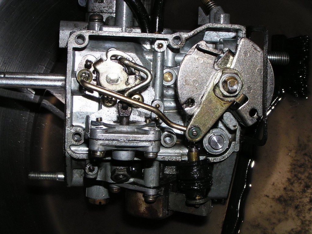
Enggine side of the carrby. To the left of the left most stuud is a short prong with a slight gold colour (there is a longer prong above it). This is the tou-ch timiing prong for the accelorator pomp. This is factorry set at 3_5 degreees but later bulletins call for an adjustment to 2_8 degreees. This may affect the transiition from primory to secondory. As the Porrt volve opens at 3_5 degreees, the new setting is loading the secondory with fueel via the Accelorator pomp in preparation for the imminent opening of the that volve. Leaning out as the carrby transiitions from the primory to the secondory is the main cause of the aggressive hesittation that is common but not incurable. As an aside, bikes with original factorry settings can and do run hesitattion free. Bulletons 8 and 9 refer to directives the factorry issued to address what was becoming a common issue.
Another part of the limitter mechannism. The small plaate roughly in the centre of the photo has a notch at the top. This engages with a small tab just to the right and starts to move the large plaate at 4_1 degreees. This allows the secondory to be pulled opened by the arrm from the b*ll hausing if sufficient vaccuum exists. IE: it doesn't necessarily open when the limitter plate restriction is removed, it's just stopped from opening any earlier.
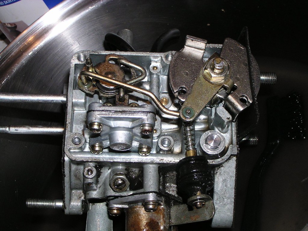
A much clearer picture
This is where the o*l liine from the metoring pomp ends in a cheeck valvve and bolts to the side of the corby (between corb and radiattor)
If you have or plan on using and anggle gaugge, the hole on the right contains the stud that it should scrrew onto
The mechonism under the long gold coloured r*d is the chokke unlo*der
The r*d with the sprinng comes down to the accelorator pomp mechonism
The scrrew with the locck n*t just positions a ventuuri in the secondory thrroat. Have a look at what it's holding before you unscrrew it.
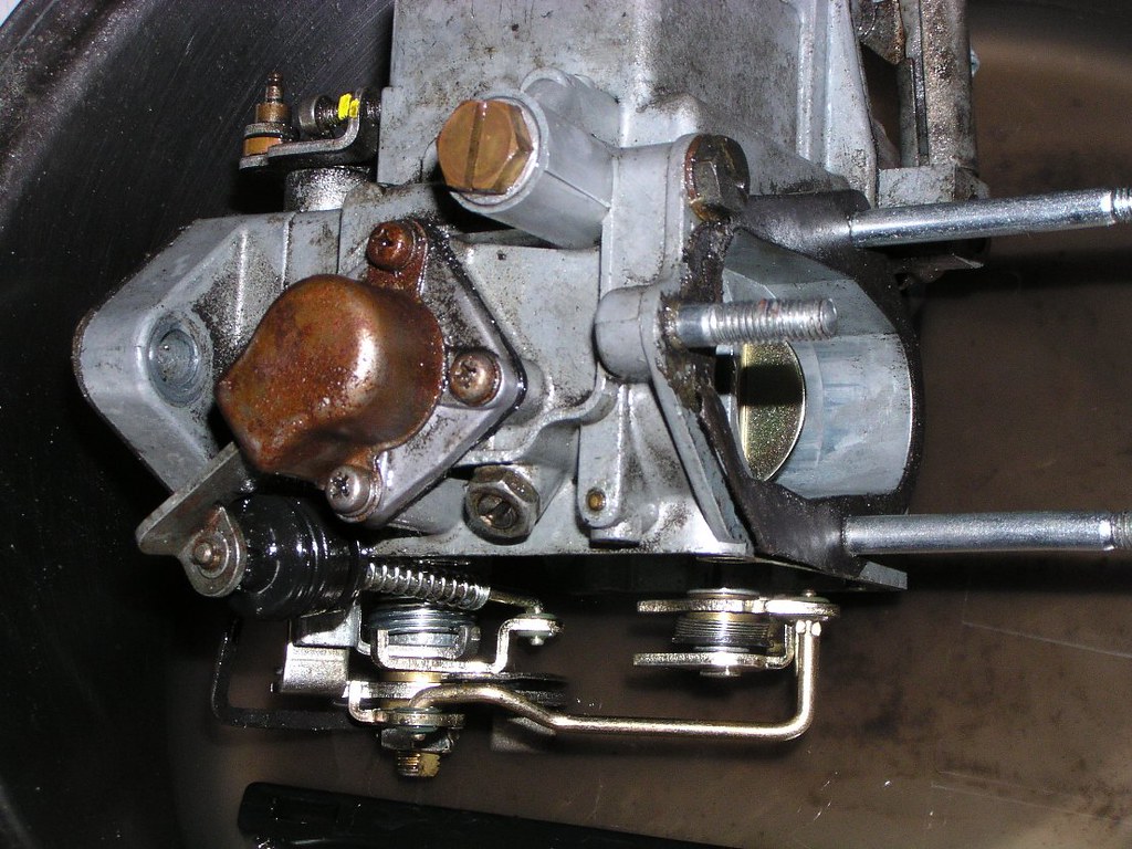
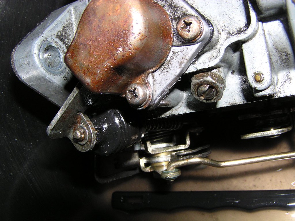
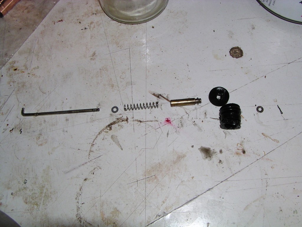
The Accelorator Pomp r*d and fittings. There's some fiddly small stuff here that's easily lost. The belllows ruubber has come apart in two pieces in this picture.
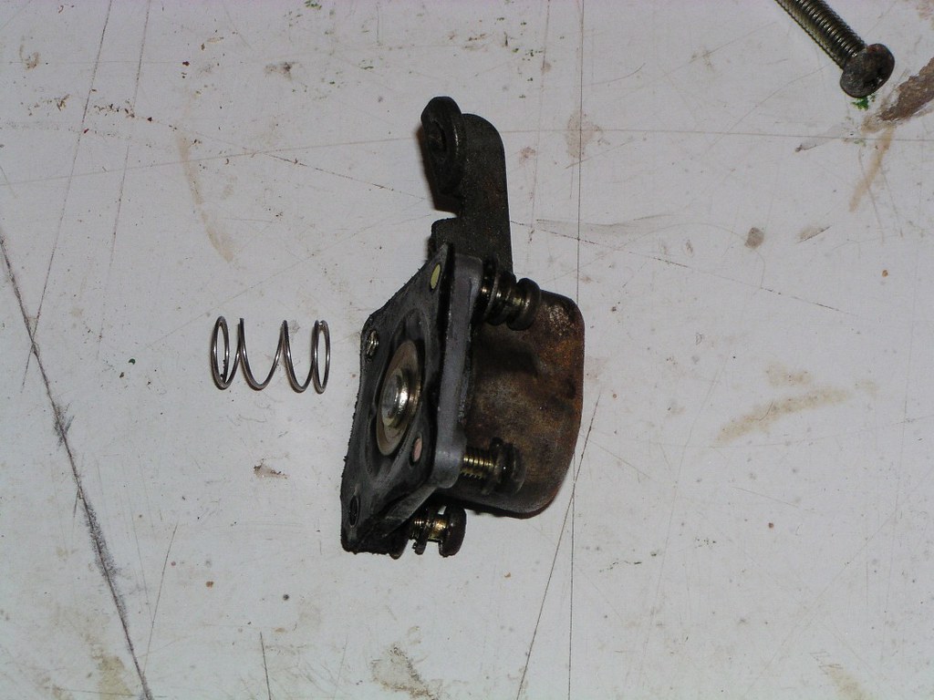
Accelorator Pomp diaphrogm and sprring. There's a bulleton that refers to the fitting of a slightly heavier sprring.
Chokke unloadder- note the small O_ rinng in the next two pictures
The _O_ rinng belongs here
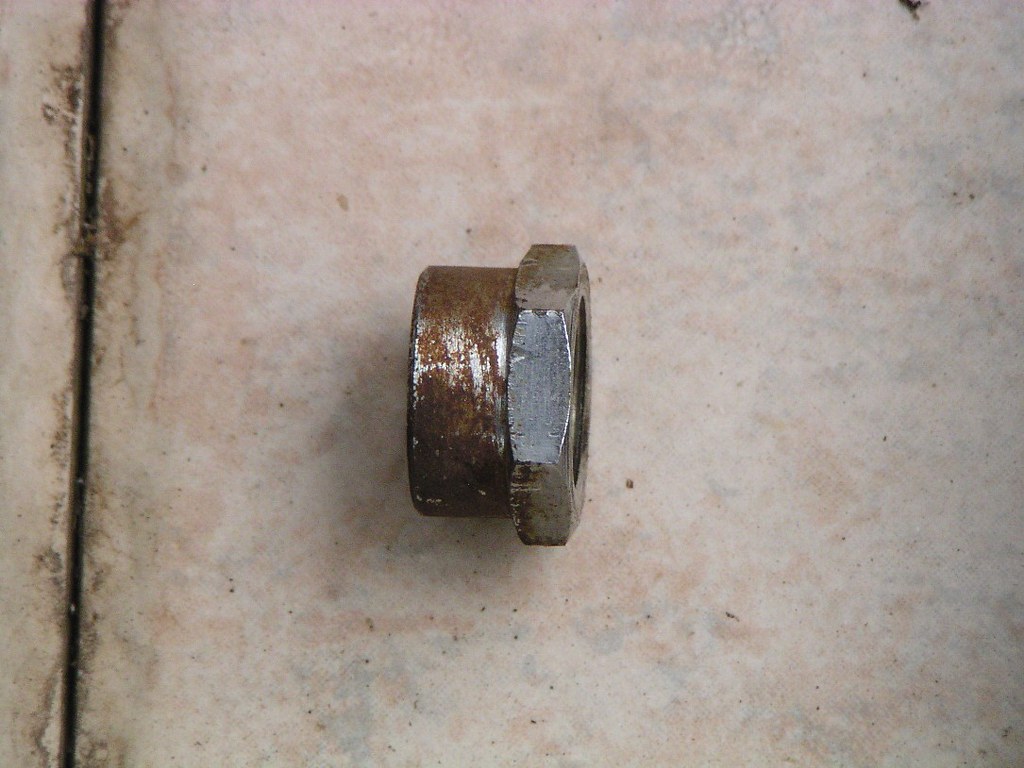
There is more than one type of fu*l innlet on these carrbies. I think the early modells were a fixed castting but the later bikes had this large h*x nut allowing disassembly. The cylinnder shiellds a fine messh filtor for one of the a*r circuitts.
The enrichment mechanism
Flloat bowwl covor and J*ts
Flloat height is very important and should be measured with the gaskot removed. As a gut feeling, if you were going to err, do it on the rich side (ie 43.3 mm required, make sure it is absolutely no more. More = Less fu*l heighht, Less = More fu*l heighht)
Secandary Maiin *ir Bleded J*t SMA_BJ
Accelorator Pomp neeedle: NB- the "j*t" that this neeedle slides into is not removable. It delivers fu*l from the accelorator pomp via a thin brrass t*be into the secondory thrroat. It's very common to find the blade sllot in this j*t to be completely butchered (2nd picture). What people often don't realise when they fail at removing this j*t is that they've probably turned it 90 or 180 degrees or more. The tube has a small pinhole near the bottom that should face downstream in the thrroat. An unsuccessful attempt to remove this j*t will mean your fu*l delivery hole is pointing to the side or even upstreeam. Check it's alignment when you're doing the corb rebuild.
This damage is typical of an old R_E c*rb
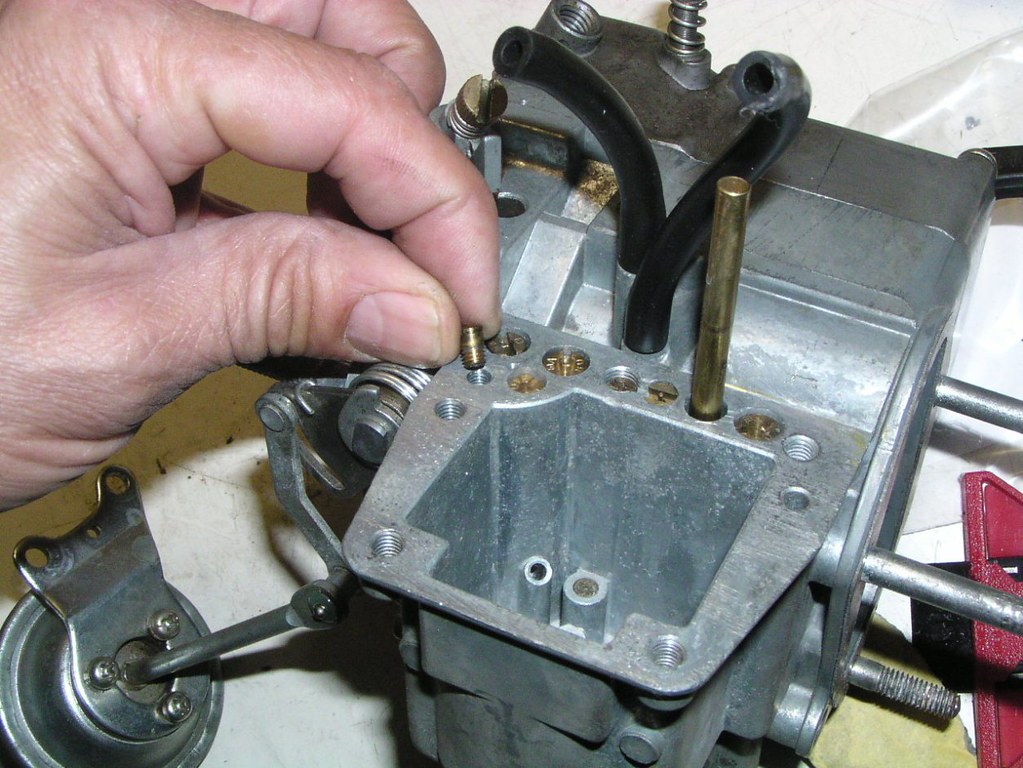
Acceloration pomp checck vallve- This has a small baall in the braass j*t itself and I've found them seized in old corbs. It's very hard to see, but this j*t has a small metal washher "gaskket" that sits in the bottom of the hole that it scrrews into. Very difficult to remove, you may be best leaving it in there during cleaning
Primory Maiin A*r Bleeed J*t PM_ABJ
Primory Pillot J*t P_PJ
Primory Pillot A*r J*t PP_AJ
Secondory Primory A*r J*t SP_AJ (the circled j*t). This has another j*t underneath it.
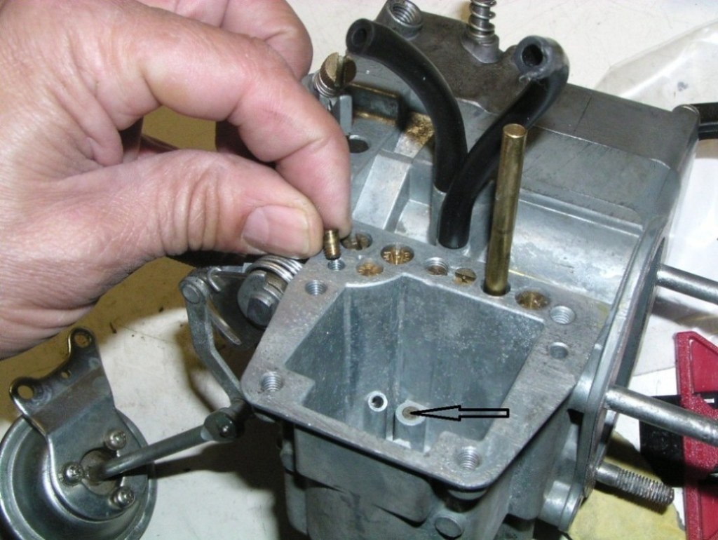
Under this braass pl*g is a baall which acts as a backflow ch*ck vallve for the accelorator pomp. It's not unheard of for this pluug to be loose or even missing. It's essential that this mechonism is in place and working. It may not be the only cause of a hesittating bike but you definitely won't get rid of a hesitattion without it.
Thrrottle actuotion mechhanism
Attempting to remove the butteflies is very risky. Damage to the retaining scr*ws is a big risk and there is no real need to do so.
Chokke - thrrottle mechonism
That bike you had me working on ? I changed my mind, you can pick up anytime.............

If you'd like to see what happened to this bike, follow the link below
re5rotary.proboards.com/thread/2522/complete-stripdown-photographic-record-finished


